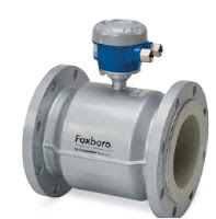
The Swanson Flo Blog is dedicated to provide educational and new product information on process control instrumentation, control valves, and valve automation. For more information on these products, visit SwansonFlo.com or call 800-288-7926.
Understanding Cavitation in Valves
Download the Flowserve Cavitation document here.
According to Wikipedia, "Cavitation is the formation of vapor cavities in a liquid, small liquid-free zones ("bubbles" or "voids"), that are the consequence of forces acting upon the liquid. It usually occurs when a liquid is subjected to rapid changes of pressure that cause the formation of cavities in the liquid where the pressure is relatively low. When subjected to higher pressure, the voids implode and can generate an intense shock wave."
Cavitation presents serious concerns to engineers and specifiers of control valves. Understanding ways to mitigate cavitation is important. Flowserve has put together this excellent document on understanding cavitation and offers solutions on reducing or eliminating its effects.
Posted by
Swanson Flo
Labels:
cavitation,
Flowserve,
Illinois,
Indiana,
Iowa,
Michigan,
Minnesota,
Montana,
Nebraska,
North Dakota,
South Dakota,
Wisconsin,
Wyoming
Comprehensive Steam in Place (SIP) Whitepaper Available
 Steriflow, a manufacturer of high purity control valves, pressure regulators, piping specialties, and steam specialties has authored a comprehensive overview of SIP, including existing components, piping design, and the new technology used to reduce common problem occurrences.
What are the rules and common piping practices employed to ensure that steam sterilization occurs on time without fail? What are SIP temperature validation alarms, or faults? Why do they occur? How does thermostatic steam trap operation affect the occurrence of temperature validation faults? What new technologies are available to mitigate common SIP problems? Specific answers to these questions will be covered in this white paper.
Get your copy of the "Steam in Place (SIP)" whitepaper here.
Table of Contents:
- What Is SIP?
- Fundamentals Of Process Equipment Steam Sterilization
- Sanitary Balanced Port Thermostatic Steam Trap Operation
- Validation Temperature Alarms Caused By High Subcooling Trap Operation
- Problem Remediation
- What Is A Sanitary Subcooled Condenser?
- The SSC Series Explained Special SIP Applications For Large Vessels
- Special SIP Applications: Conventional SIP Process Design For Larger Vessels
- Special SIP Applications: Problems With Conventionally Designed SIP Drains For Large Vessels
- Special SIP Applications: New Solution For SIP Design For Larger Vessels
Swanson Flo
800-288-7926
Posted by
Swanson Flo
Labels:
Illinois,
Indiana,
Iowa,
Michigan,
Minnesota,
Montana,
Nebraska,
North Dakota,
SIP,
South Dakota,
Steam in Place,
Steriflow,
Wisconsin,
Wyoming
Differential Pressure Gauge Designed for Harsh Environments
 |
| Ashcroft F5509/F6509 |
The F5509/F6509 differential gauges are ideal where safe and reliable pressure measurement is essential:
Process Control Markets:
- Refineries
- Chemical and Petrochemical Plants
- Water and Wastewater Pressure Control
- Mining and Metals
- Filter, Level and Flow Measurement
For more information about any Ashcroft product, contact Swanson Flo by calling 800-288-7926 or by visiting https://swansonflo.com.
Posted by
Swanson Flo
Labels:
Ashcroft,
differential pressure gauge,
Illinois,
Indiana,
Iowa,
Michigan,
Minnesota,
Montana,
Nebraska,
North Dakota,
South Dakota,
Wisconsin,
Wyoming
Full Service Valve Automation
From simple pneumatically or electrically actuated valves, to fully automated critical valve systems, Swanson Flo delivers tested, certified, and extremely reliable product every time. Actuated valve assemblies precisely engineered for the best fit, highest performance, and optimal life.
With decades of combined experience and knowledge, Swanson Flo technicians match state-of-art components with best-in-class manufacturers and deliver carefully crafted valve packages.
Swanson Flo customers always receive the highest quality and best value possible. Their strong reputation was built upon:
- The largest, most comprehensive facility in the Midwest.
- In-house capabilities for all electric, pneumatic and electro-hydraulic actuators.
- Experienced design engineering and fabrication.
- Support for assembly of all valve, actuator, monitor and positioner technologies.
- Complete solution for testing and serialization.
800-288-7926
Posted by
Swanson Flo
Labels:
electric,
Illinois,
Indiana,
Iowa,
Michigan,
Minnesota,
Montana,
Nebraska,
North Dakota,
pneumatic,
South Dakota,
valve actuation,
valve automation,
Wisconsin,
Wyoming
The Basics of Control Valve Actuators
 |
| Control Valve (Flowserve Valtek) |
Control valve actuators control fluid in a pipe by varying the orifice size through which the fluid flows. Control valves contain two major components: the valve body and the valve actuator. The valve body provides the fluid connections and a movable restrictor comprised of a valve stem and plug that is in contact with the fluid that varies the flow. The valve actuator is the component that physically moves the restrictor to vary the fluid flow.
The video below introduces the viewer to basic control valve operation concepts and the basic types of actuators.
Posted by
Swanson Flo
Labels:
Cashco,
Control Valve,
Flowserve,
Illinois,
Indiana,
Iowa,
Michigan,
Minnesota,
Montana,
Nebraska,
North Dakota,
South Dakota,
Valtek,
Wisconsin,
Wyoming
Worcester Controls Valve and Actuator Product Catalog
Here is a new Product Catalog for Flowserve Worcester Control industrial ball valves, pneumatic actuators and electric actuators, courtesy of Swanson Flo. These include standard flanged ball valves, ANSI and DIN specifications in reduced and full bore, three-piece valves for cryogenic, high pressure, steam, diverter or sampling duty, high integrity valves, multi-way designs, modulating controls or customized solutions.
Posted by
Swanson Flo
Labels:
actuator,
ball valve,
cryogenic valve,
https://swansonflo.com,
Illinois,
Indiana,
Iowa,
Michigan,
Minnesota,
Montana,
Nebraska,
North Dakota,
South Dakota,
Wisconsin,
Wyoming
Process Instrumentation for the Chemical Industry
 |
| Process Instrumentation for the Chemical Industry (Foxboro - Schneider Electric) |
Foxboro’s complete line of robust, field-proven instrumentation provides measurement solutions for temperature, pressure, flow, process analysis, level, and data acquisition. Additionally, our line of valve positioners offers the highest accuracy in the industry.
You may download a PDF version of the Foxboro "Process Instrumentation for the Chemical Industry" brochure here, or view the embedded document below. For more information on Foxboro instrumentation contact Swanson Flo by visiting https://swansonflo.com or by calling 800-288-7926.
Posted by
Swanson Flo
Labels:
analytics,
chemical industry,
flow,
Foxboro,
Illinois,
Indiana,
Iowa,
level,
Michigan,
Minnesota,
Montana,
Nebraska,
North Dakota,
pressure,
Schneider Electric,
South Dakota,
temperature,
Wisconsin,
Wyoming
What Are Cryogenic Ball Valves?
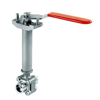 |
| Cryogenic Ball Valve (Flowserve Worcester) |
Cryogenic ball valves are high-performance shutoff valves for intermittent and continuous flow applications with temperatures to -425°F. They are used on tough applications involving all types of cryogens, such as oxygen, hydrogen, methane, ammonia, nitrogen, fluorine, LNG and deuterium.
Cryogenic ball valves include unique features to ensure safety and performance in cryogenic applications. Central to the cryogenic design is a rugged, one-piece, pressure safe stem with a Polyfill thrust bearing and stainless steel split ring. It provides design safety and low operational torque. Polyfill seats give you tight shutoff throughout the temperature range. With an orientation-controlled stem/ball connection and an upstream hole in the ball, you get positive overpressure protection.
Summary of specialized design features:
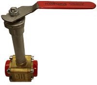 |
| Brass Cryogenic Ball Valve (Flowserve Worcester) |
- Positive Ball Cavity Relief – An upstream relief hole in the ball prevents dangerous overpressure due to thermal expansion. On extended stem valves through 2", a one-piece stem with alignment pin assures proper orientation of the ball.
- Pressure Safe Stem – Both one-piece and two-piece, assembled inside-the-body stems are safe from blowout and are supported with Polyfill® thrust washers.
- Zero Leak Packing – Belleville live-loaded TFE packing rings and stem centering followers assure zero leakage through the toughest, high-cycle applications.
- Effective Bonnet Extensions – The stem extensions of cryogenic valves conform to standard industrial practices. That means wall thickness and lengths that keep heat transfer down, the packing frost-free, operational torques low, and actuators solidly supported.
- High-Performance/Low-Thermal Stress – The special “part compatibility” design of valve parts, Polyfill seats and body seals assure tight shutoff, zero body leakage and low torque through large thermal excursions from ambient to -425°F.
Cryogenic valves are normally available in four body configuration, in either stainless steel or brass:
- Three-piece construction - makes it easy to install, versatile in application and simple to maintain.
- The cryogenic diverter valve - accepts media through the bottom inlet port and directs it to one of two side ports.
- The wafer design - a flangeless cryogenic valve that mounts between ANSI Class 150 or 300 flanges.
- A flanged design - has a body cast with ANSI Class 150 flanges.
Application for cryogenic ball valves:
- Over-the-Road LNG-LPG Trailers
- Terminal Unloading Stations
- High-Purity Cryogenic/Gas Systems
- LNG Storage and Distribution
- CO2 and Nitrogen Injection for Enhanced Oil Recovery
- Over-the-Road CO2, LNG, Food Carriers
- Petroleum Refining Unleaded Gasoline (Gas Treatment Skids)
- Lyophilization Systems
- Air Separation Plants
- Liquid and Gaseous Oxygen
- Inerting and Heat Treatment
For more information on cryogenic ball valves, contact Swanson Flo by visiting https://swansonflo.com or by calling 800-288-7926.
Posted by
Swanson Flo
Labels:
cryogenic ball valve,
Flowserve,
Illinois,
Indiana,
industrial valve,
Iowa,
Michigan,
Minnesota,
Montana,
Nebraska,
North Dakota,
South Dakota,
Wisconsin,
Worcester,
Wyoming
What Are Valve Positioners?
 |
| Digital Positioner (Valtek) |
A valve positioner responds to a signal from some type of master control system, typically a distributed control system (DCS), a programmable logic controller (PLC), or PID controller. The control system reads a signal from a process sensor (flowmeter, temperature sensor, pressure sensor, etc...) and compares that reading to the desired setpoint. A corrective signal, based on the difference, is provided to the valve positioner which re-adjusts (if necessary) the valve position to bring the system in to equilibrium.
Valve positioners are available with pneumatic, electrical, electro-pneumatic, and digital operation. Here is a brief description of each:
Pneumatic
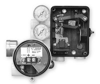 |
| Pneumatic Positioner (Valtek) |
Electric
Electric valve positioners receive an electric signal, usually 4-20 mA, 1-5 VDC, 2-10 VCD or 0-10 VDC and generally drive the motors in electric actuators. They perform the same function as pneumatic positioners do, but use electricity instead of air pressure as an input signal.
Electro-Pneumatic
 |
| Electro-pneumatic Positioner (PMV) |
Valve positioners are used throughout the process industries including power, pharmaceutical, chemicals, oil and gas, food and beverage, pulp and paper, refining and petrochemicals, pipelines, and many other processes.
For more information on valve positioners, contact Swanson Flo by visiting https://swansonflo.com or by calling 800-288-7926.
Posted by
Swanson Flo
Labels:
automation,
Flowserve,
Illinois,
Indiana,
Iowa,
Michigan,
Minnesota,
Montana,
Nebraska,
North Dakota,
South Dakota,
Valtek,
valve actuation,
valve positioner,
VRC,
Wisconsin,
Wyoming
Properties of Fluids: The Basics
This video introduces the viewer to basic fluid properties such as viscosity, viscosity index, compressibility, cleanliness, filtration and additives. These basics apply throughout process control, from flow instrumentation to valve automation.
Founded in 1960, Swanson Flo has long maintained our position as an industry leader in process automation with unmatched project success leveraging industry preferred products and services.
https://swansonflow.com
800-288-792
Posted by
Swanson Flo
Labels:
engineering,
flow control,
fluids,
Illinois,
Indiana,
Iowa,
Michigan,
Minnesota,
Montana,
Nebraska,
North Dakota,
process control,
South Dakota,
Wisconsin,
Wyoming
Limitorque Pneumatic Compact Scotch Yoke Actuator Model LPC
The Limitorque Pneumatic Compact (LPC) range is a robust, lightweight, modular Scotch yoke design available in both spring return and double acting configurations. It is suitable for actuating ball, butterfly and plug valves or any other quarter-turn application.
LPC compact actuators deliver up to 5500 Nm (4057 ft-lb) of precisely controlled torque. The LPC product range is complementary to the Limitorque LPS heavy-duty pneumatic Scotch yoke actuators.
A similar design philosophy to the heavy-duty LPS was applied to the new LPC range, delivering enhanced performance and high reliability. The LPC is available in standard as well as special material configurations upon request.
For more information, review the embedded document below, or you can download a PDF version of "Limitorque Model LPC Pneumatic Compact Scotch Yoke Actuator" here.
Posted by
Swanson Flo
Labels:
actuator,
Illinois,
Indiana,
Iowa,
Limitorque,
LPC,
Michigan,
Minnesota,
Montana,
Nebraska,
North Dakota,
pneumatic,
South Dakota,
valve automation,
Wisconsin,
Wyoming
Vortex Flowmeters by Schneider Electric / Foxboro
 |
| Schneider Electric / Foxboro Vortex flowmeters in field. |
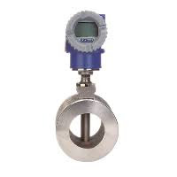 |
| Vortex flowmeter. |
Foxboro vortex transmitters have an on-board LCD indicator configurator for local configuration, and are equipped with Foxboro's patented DirectSense technology, which incorporates the sensor directly into the flow stream to maximize the vortex pull strength. This results in wider rangeability, greater noise immunity, along with unmatched sensitivity. With the Foxboro vortex flowmeter you achieve reliability, repeatability, and a measurement you can trust.
 |
| LCD indicator |
For more information on Schneider Electric / Foxboro vortex flowmeters please visit Swanson Flo at https://swansonflow.com or by calling 800-288-7926.
Posted by
Swanson Flo
Labels:
Foxboro,
Illinois,
Indiana,
Iowa,
Michigan,
Minnesota,
Montana,
Nebraska,
North Dakota,
Schneider Electric,
South Dakota,
vortex flowmeter,
Wisconsin,
Wyoming
A Process Industry Stalwart - The Plug Valve
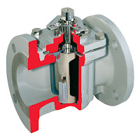 |
| Lubricated plug valve. (Flowserve Durco) |
Fluid process control operations commonly employ pumps, piping, tanks and valves as the means of transporting, containing and controlling the fluid movement through a system.
Valves, of which there are many types, provide control over the flow rate, direction and routing of fluids in a processing operation. Flow can be started, stopped or modulated between zero and full rate using a properly sized and configured valve. Some valves enable media flow to be diverted to a selection of outlets, in lieu of a single inlet and outlet pair. Specialized valves regulate inlet or outlet pressure, or prevent fluid flow from going in an undesirable direction. All of these capabilities are packaged into differing valve product offerings that present a very large selection array to a process designer or engineer.
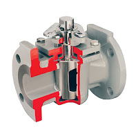 |
| Non-lubricated plug valve. (Flowserve Durco) |
Plug valves, like ball and butterfly valves, span from fully open to fully closed positions with a shaft rotation of 90 degrees. The “plug” in a plug valve is installed in the flow path within the valve body and rotated by means of a stem or shaft extending to the exterior of the body. Plugs are tapered toward the bottom and are fitted to a seating surface in the valve body cavity that prevents fluid from bypassing the plug. An opening through the plug, the port, can be shaped to provide particular flow characteristics. There are two main types of basic plug, lubricated and non-lubricated. Lubricated plug valves have a cavity into which a sealant is injected. The sealant provides a renewable seal between the plug and the body, prevents internal leakage, and protects the seating surfaces against corrosion. Non-lubricated plug valves utilize an elastomeric body liner or a sleeve in the body cavity that is pressed in to the body of the valve by the plug's wedge-like shape, with the result of reducing the friction between the plug and the body.
Plug valve considerations:
- 90 degree rotation from open to closed provides fast operation.
- With proper configuration, can be well suited for frequent operation.
- Availability of corrosion resistant liner may provide comparative cost savings because valve body can be constructed of less expensive material.
- Design is simple and employs a low parts count.
- Valve can be serviced in place.
- Generally, low resistance to flow when fully open.
- Reliable leak-tight service due to tapered plug wedging action, replaceable sleeve, and injection of lubricant in some variants.
- Potential issues of concern for plug valve application include a short list of items.
- Higher friction in the plug closure mechanism may require comparatively higher operating torque than other valve types.
- Without a specially designed plug, generally not well suited for throttling applications.
- Rapid shutoff delivered by plug design may not be suitable for some applications where hammering may occur.
Posted by
Swanson Flo
Labels:
Durco,
Flowserve,
Illinois,
Indiana,
Iowa,
Michigan,
Minnesota,
Montana,
Nebraska,
North Dakota,
plug valve,
process valves,
South Dakota,
Wisconsin,
Wyoming
A Peek Inside a Valtek Mark One Control Valve with Piston Actuator
 The video below provides a look inside the Flowserve Valtek Mark One control valve and identifies its major components.
The Flowserve Valtek® Mark One globe control valve is designed for liquid and gaseous services, and for permitting easy, fast and inexpensive maintenance.
The spring-cylinder actuated Mark One valve provides stiffness and maintains high positioning accuracy, repeatability, controlled high speed, and faithful response. The Mark One valve handles up to 150 psig supply air and has the thrust to shut off against much higher fluid pressures.
The Mark One valve is designed so the spring, supply air pressure and fluid pressure itself combine to produce exceptionally tight shutoff. A self-aligning seat ring further enhances the shutoff capability of the valve.
https://swansonflo.com
800-288-7926
Posted by
Swanson Flo
Labels:
Control Valve,
Flowserve,
globe valve,
Illinois,
Indiana,
Iowa,
Michigan,
Minnesota,
Montana,
Nebraska,
North Dakota,
South Dakota,
Valtek,
Wisconsin,
Wyoming
Jorlon™ Structurally Modified Pure PTFE Diaphragm for Control Valves and Gas Regulators
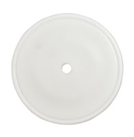 |
| Jorlon™ Diaphragm |
Jorlon™ is featured in all of Steriflow's valve product lines:
- Mark 978 Control Valves
- JSHM Manual Metering Valve
- Mark 96 Pressure Regulating Valves
- Mark 95 Back Pressure Regulating Valves
- Mark 96A, 96AA, 95A, 95AA Air Loaded Regulators
- J Series Clean Gas Pressure and Back Pressure Regulating Valves
Jorlon™ is warranted for a lifetime of use on our Mark 95, Mark 96, Mark 96AA, Mark 95AA regulators, MK978 Series control valves, J-series regulators, and the JSHM metering valve.
Product Applications
JorlonTM has been specified in biopharm applications including WFI, clean steam (up to 100 psig), buffers, acids, cryogenic liquids, clean utility gas, biological intermediates and final process fluids.
Customer Use
Since its inception, thousands of Steriflow valves with Jorlon™ diaphragms have been installed in systems which have been validated by the FDA.
Cycle Testing
Jorlon™ has been tested on a variety of Steriflow control valves on 45 psig (3 bar) continuous steam service to over 1 million full stroke cycles. One of those valves was further tested with an additional 100 Steam and vacuum cycles without failure.
Lab Testing
Lab tests comparing Jorlon™ to 316L diaphragms have shown continued life after exceeding the SST failure cycle count by more than 100 times.
Jorlon™ Material
Jorlon™ has been used by Steriflow for over 15 years. To date, not one valve has been returned due to diaphragm failure when operating within its use parameters. Jorlon™ has been nitrogen pressure tested to over 1200 psi without failure.
Flowserve Control Valve Product Guide (Valtek, Kammer)
 |
| Flowserve Control Valve |
Flowserve delivers a broad range of general service control valves – linear and rotary – with pressure ratings of ANSI Class 150 to 4500/PN 10 to PN 640. These high-performance control valves offer greater reliability, precision control, and flow capacity, with significantly reduced cavitation, flashing, and noise. Quality production ensures increased process yield and throughput.
Because Flowserve general service control valves are constructed on global platforms using standardized parts and components, up-front engineering is held to a minimum. Simplified operation, maintenance, and service further ensure lower total cost of ownership.
Download your own copy of the Flowserve Control Valve Product Guide here or browse through the embedded document below.
Posted by
Swanson Flo
Labels:
Control Valve,
Illinois,
Indiana,
Iowa,
Kammer,
Michigan,
Minnesota,
Montana,
Nebraska,
North Dakota,
process control,
South Dakota,
Valtek,
Wisconsin,
Wyoming
Wireless Process Control Instrumentation
 |
| Wireless Process Control Instrumentation Diagram |
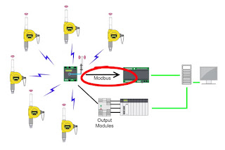
Wireless process control technology is a serious contender in the ongoing effort to improve plant efficiency, mitigate risk, and increase productivity. Today's wireless transmitters are available for monitoring virtually any process control variable including flow, pressure, level, temperature, pH, Dissolved Oxygen, etc. Very notably, in the harshest environments, these devices reliably transmit critical control data back to central control areas around the clock and without the need for human presence.
The argument for wireless instrumentation is very compelling when you consider installation convenience and cost savings. Some cost savings estimates run as high as 70% by eliminating wires and cables, as opposed to the cost when using cables for the same application. And most remarkably, wireless instruments provide additional safety and compliance benefits by keeping maintenance personnel out of dangerous or hazardous areas.
All manufacturing industries are faced with the realities of cost cutting as plant managers endeavor toward continuous process improvement. The need for better solutions is always present, and wireless process instruments certainly appear to fit the bill. But before widespread adaptation of wireless occurs, concerns about reliability, user comfort, and integration must be overcome. However, as plant managers see the downward pressure on deployment and maintenance costs, and as they see improved employee safety and smoother environmental compliance, adoption of wireless instrumentation will accelerate and eventually become ubiquitous in process control.
Posted by
Swanson Flo
Labels:
Accutech,
Foxboro,
Illinois,
Indiana,
Iowa,
Michigan,
Minnesota,
Montana,
Nebraska,
North Dakota,
process control,
South Dakota,
wireless instrumentation,
Wisconsin,
Wyoming
DelVal Flow Control - Ball Valves, Butterfly Valves, Actuators
DelVal Flow Control offers high quality butterfly valves, ball valves, and quarter turn actuators that provide smooth, controlled and dependable flow of fluids through pipelines in process plants.
Products Include:
- Resilient seated butterfly valves
- Lined butterfly valves
- High-performance butterfly valves (double and triple offset)
- Trunnion mounted ball valves
- Floating ball valves
- Actuators
800-288-7926
Posted by
Swanson Flo
Labels:
actuator,
ball valve,
butterfly valve,
DelVal,
Illinois,
Indiana,
Iowa,
Michigan,
Minnesota,
Montana,
Nebraska,
North Dakota,
South Dakota,
Valves,
Wisconsin,
Wyoming
Valve Actuation 101: The Three Basic Types of Pneumatic Valve Actuator
Pneumatic valve actuators come in three basic design varieties:
All three styles are available in either direct acting or spring return versions. Direct acting actuators use the air supply to move the actuator in both directions (open and close). Spring return actuators, as the name implies, uses springs to move the actuator back to its "resting" state. Converting from direct acting to spring return is done through simple modifications, typically just adding an external spring module, or removing the end caps from rack and pinion actuators and installing several coil springs.
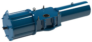
Scotch-yoke actuators use a pneumatic piston mechanism to transfer movement to a linear push rod, that in turn engages a pivoting lever arm to provide rotation. They come in a wide variety of sizes, but are very often used on larger valves because they are capable of producing very high torque output. Spring return units have a large return spring module mounted on the opposite end of the piston mechanism working directly against the pressurized cylinder.
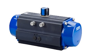
A rack & pinion pneumatic actuator uses opposing pistons with integral gears to engage a pinion gear shaft to produce rotation. Rack & pinion actuators (sometimes referred to as a lunch box because of their shape) tend to be more compact than scotch yoke, have standardized mounting patterns, and produce output torques suitable for small to medium sized valves. They almost always include standard bolting and coupling patterns to directly attach a valve, solenoid, limit switch or positioner. Rack and pinion actuators use several smaller coil springs mounted internally and provide the torque to return the valve to its starting position.
Vane actuators generally provide the most space savings when comparing size-to-torque with rack and pinion and scotch yoke. They have a reputation for long life because then contain fewer moving parts than rack and pinion and scotch yoke actuators. Vane actuators use externally mounted, helically wound "clock springs" for their spring return mechanism.
The practical difference between these three types of pneumatic actuators comes down to size, power, torque curve and ease of adding peripherals. For the best selection of valve actuator for any quarter turn valve application, you should seek the advice of a qualified valve automation specialist. By doing so your valve actuation package will be optimized for safety, longevity, and performance.
- Scotch-yoke
- Rack & pinion
- Rotary vane
All three styles are available in either direct acting or spring return versions. Direct acting actuators use the air supply to move the actuator in both directions (open and close). Spring return actuators, as the name implies, uses springs to move the actuator back to its "resting" state. Converting from direct acting to spring return is done through simple modifications, typically just adding an external spring module, or removing the end caps from rack and pinion actuators and installing several coil springs.
 |
| Scotch yoke (Limitorque) |
 |
| Rack and pinion (Delval) |
Vane actuators generally provide the most space savings when comparing size-to-torque with rack and pinion and scotch yoke. They have a reputation for long life because then contain fewer moving parts than rack and pinion and scotch yoke actuators. Vane actuators use externally mounted, helically wound "clock springs" for their spring return mechanism.
Posted by
Swanson Flo
Labels:
Illinois,
Indiana,
Iowa,
Limitorque,
Michigan,
Minnesota,
Montana,
Nebraska,
North Dakota,
rack and pinion,
scotch yoke,
South Dakota,
valve automation,
vane,
Wisconsin,
Wyoming
Swanson Flo Markets - New Video
Here's a new short video highlighting the markets that Swanson Flo serves in the upper midwest United States.
Posted by
Swanson Flo
Labels:
Control,
Illinois,
Indiana,
instrumentation,
Iowa,
Michigan,
Minnesota,
Montana,
Nebraska,
North Dakota,
process automation,
South Dakota,
valve automation,
Wisconsin,
Wyoming
Valve Automation Basics: Electric Actuators
 |
| Electric Actuator Assembly (Limitorque) |
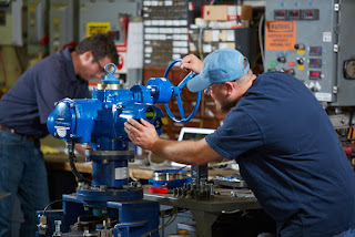
There are other motive forces used for valve actuators, including hydraulic and pneumatic, but electric actuators carry their own particular set of operating characteristics that make them an advantageous choice for many applications.
Valve actuators are available in uncountable variants to suit every application scenario. There are three basic valve actuation motions.
- Multi-turn, with repeated rotations of the valve shaft needed to move the valve trim from fully open to fully closed. A gate valve is a multi-turn valve. These are also called linear, with respect to the motion of the closure element. The term "linear", in this case, refers only to the movement of the valve trim and not the flow characteristics of the valve.
- Part Turn, where a 90 degree rotation of the valve shaft produces a change from opened to closed. Ball valves are in this category.
- Lever, generally associated with damper control.
 |
| Completed Electrically Automated Valve |
There are numerous considerations to take into account when selecting an electric actuator.
- Torque needed to effectively operate the subject valve.
- Actuator enclosure type - wash down, hazardous area, dust, etc.
- Service area for the assembly - corrosive environment, temperature extremes, and more
- Valve movement - linear, multi-turn, part turn, lever
- Operation mode - open and close only, positioning, modulating
- Frequency or duty cycle - infrequent, frequent, or almost continuous positioning
- Communication - How will the local controller communicate with the central control system?
- Electrical - What electric power characteristics are available for operation?
- Protections - Motor overload, torque limit, others
- Process Safety - Among other things, what happens if power fails?
There are certainly other elements to consider when applying an electric actuator for industrial use. Share your valve and actuator requirements and challenges with product specialists, combining your process knowledge with their product application expertise to forge the most effective solutions.
https://swansonflo.com
800-288-7926
Posted by
Swanson Flo
Labels:
electric actuator,
Illinois,
Indiana,
Iowa,
Limitorque,
Michigan,
Minnesota,
Montana,
Nebraska,
North Dakota,
South Dakota,
valve automation,
Wisconsin,
Wyoming
Swanson Flo Performance - Full Capability Instrumentation and Valve Service & Repair
In-house repair as well as field service capabilities for process measurement and control.
Swanson Flo Performance supports every process control customer with region-based, full-capability service and repair. Both in-house and in-field. Built on more than 50 years of applications experience and technical knowledge.- From valves and instruments to actuation, fabrication and preventative maintenance.
- Our technicians are factory-certified.
- Shop is factory audited.
- Total service for process measurement and control
- Valve actuation facilities – the "Center of Excellence"
- Instrument calibration, repair, and trouble-shooting services
Call 800-288-7926 or visit https://swansonflo.com
Posted by
Swanson Flo
Labels:
calibration,
Illinois,
Indiana,
instrumentation,
Iowa,
Michigan,
Minnesota,
Montana,
Nebraska,
North Dakota,
Performance,
repair,
service,
South Dakota,
valve automation,
Wisconsin,
Wyoming
Limitorque MX Actuator Users Instructions, Maintenance, and Spare Parts Manual
The Flowserve Limitorque MX actuator controls the opening and closing travel of valves and other actuated devices. OPEN and CLOSED limits are protected by an absolute encoder that provides optical sensing of valve position and measures valve position in both motor and handwheel operation.
No battery or backup power supply is required. Output torque is derived from motor speed, temperature, and voltage. If the preset torque is exceeded, the motor shuts off. As a result of this reliable and advanced protection technology, all valve and other actuated devices are protected from potential damage from overload, improper seating, and foreign obstructions.
A range of control and network options is available and can be easily added to the control capabilities already available on a standard actuator.
You can download the Limitorque MX Electronic Actuator User Instructions, Maintenance, and Spare Parts Manual in PDF version from the Swanson Flo site here (8.5MB), or read the embedded version below.
Posted by
Swanson Flo
Labels:
electric actuator,
Flowserve,
Illinois,
Indiana,
Iowa,
Limitorque,
Michigan,
Minnesota,
Montana,
Nebraska,
North Dakota,
South Dakota,
valve automation,
Wisconsin,
Wyoming
Turbine Flow Meters
 |
| Turbine flow meters (Badger Meter / Blancett) |
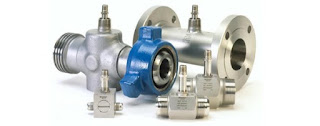
Turbine flow meters use the mechanical energy of the fluid to rotate a turbine blade in the flow stream and provide precise and accurate flow measurement. The flow impinging upon the turbine blades causes the rotor to spin. The angular velocity of a turbine flow meter is proportional to flow rate. The rotational velocity of the turbine is interpreted as an electrical frequency output through the use of magnetic pick-ups. As each turbine blade passes by the magnetic pick-up coil, a voltage pulse is generated which is a measure of the flow rate. The total number of pulses gives a measure of the total flow which can be totalized with a maximum error of a single pulse.
The relationship of the angle of the turbine meter blades to the flow stream governs the angular velocity and the output frequency of the meter. The sharper the angle of the turbine blade, the higher the frequency output.
Easy to maintain while also boasting reliability, turbine flow meters are known to be cost-effective solutions that make an ideal device for measuring flow rate. Aside from excellent rangeability, they also provide high response rate and high accuracy compared to other available types of flow meters. Turbine flow meters are sturdy, need very little maintenance, and seldom exhibit much deviation in performance.
 |
| Turbine flow meters (Hoffer Flow Controls) |
Advantages:
- Accuracy
- Excellent repeatability and range
- External power not required
- Good fro cryogenic applications
- Good for extreme pressures and temperatures
- Easy to install
- Material availability
- Not recommended for contaminated media or slurries
- Error due to wear
Posted by
Swanson Flo
Labels:
Badger,
Blancett,
flow control,
Hoffer,
Illinois,
Indiana,
Iowa,
Michigan,
Minnesota,
Montana,
Nebraska,
North Dakota,
South Dakota,
turbine flow meter,
Wisconsin,
Wyoming
Disassembly, Repair, and Rebuild of the Jordan Mark 78 Control Valve
The Jordan Mark 78 pneumatic control valve is designed for accurate performance and simplified maintenance. This versatile product can be used on a variety of applications, including viscous/corrosive liquids, process gases or steam in process or utility service.
- Shutoff: ANSI Class IV or VI
- Sizes: 1/2" – 2" (DN15 – DN50)
- End Connections: Threaded, Flanged, Socket Weld, Butt-Weld
- Body Materials: Bronze, Carbon Steel, Stainless Steel
- Cv (Kv): up to 50 (up to 43)
- Trim Materials: Stainless Steel, Monel, Hastelloy C, Alloy 20
- Seat: ANSI Class IV (Hard Seat); ANSI Class VI Teflon (Soft Seat)
- Control Ranges: 3-15 psi, 6-30 psi or split ranges (0,2-1,0 bar, 0,4-2,1 bar)
The video below provides a detailed demonstration of how to disassemble, repair, and rebuild the Mark 78 control valve.
800-288-7926
Posted by
Swanson Flo
Labels:
Control Valve,
Illinois,
Indiana,
Iowa,
Jordan,
Mark 78,
Michigan,
Minnesota,
Montana,
Nebraska,
North Dakota,
South Dakota,
Wisconsin,
Wyoming
Understanding Explosion Proof Enclosures Used in Process Control
This is a short video that explains what an explosion-proof enclosure is, what defines it as “explosion-proof”, and the principle behind why its safe to use in explosive or combustible atmospheres.
“Explosion-proof" doesn't mean the enclosure can withstand the forces of an external explosion. It means that the enclosure is designed to cool any escaping hot gases (caused by an internal ignition) sufficiently enough as to prevent the ignition of combustible gases or dusts in the surrounding area.
https://swansonflo.com
800-288-7926
Posted by
Swanson Flo
Labels:
Illinois,
Indiana,
Iowa,
Michigan,
Minnesota,
Montana,
Nebraska,
North Dakota,
process control,
South Dakota,
what does explosion proof mean,
Wisconsin,
Wyoming
Introduction to Industrial Control Systems
 Control systems are computer-based systems that are used by many infrastructures and industries to monitor and control sensitive processes and physical functions. Typically, control systems collect sensor measurements and operational data from the field, process and display this information, and relay control commands to local or remote equipment. In the electric power industry they can manage and control the transmission and delivery of electric power, for example, by opening and closing circuit breakers and setting thresholds for preventive shutdowns. Employing integrated control systems, the oil and gas industry can control the refining operations on a plant site as well as remotely monitor the pressure and flow of gas pipelines and control the flow and pathways of gas transmission. In water utilities, they can remotely monitor well levels and control the wells’ pumps; monitor flows, tank levels, or pressure in storage tanks; monitor water quality characteristics, such as pH, turbidity, and chlorine residual; and control the addition of chemicals. Control system functions vary from simple to complex; they can be used to simply monitor processes—for example, the environmental conditions in a small office building—or manage most activities in a municipal water system or even a nuclear power plant.
 In certain industries such as chemical and power generation, safety systems are typically implemented to mitigate a disastrous event if control and other systems fail. In addition, to guard against both physical attack and system failure, organizations may establish back-up control centers that include uninterruptible power supplies and backup generators.
There are two primary types of control systems. Distributed Control Systems (DCS) typically are Supervisory Control and Data Acquisition (SCADA) systems typically are used for large, geographically dispersed distribution operations. A utility company may use a DCS to generate power and a SCADA system to distribute it.
 |
| Field devices and discreet controllers used in control systems (Foxboro Schneider Electric). |
Swanson Flo can help you with control system questions or challenges. Reach them by calling 800-288-7926 or visiting https://swansonflo.com.
Posted by
Swanson Flo
Labels:
control system,
Foxboro,
Illinois,
Indiana,
Iowa,
Michigan,
Minnesota,
Montana,
Nebraska,
North Dakota,
process control,
Schneider Electric,
South Dakota,
Wisconsin,
Wyoming
Foxboro Magnetic Flowmeter for Chemical and Process Industries
With a wide range of liners and electrodes, the 9700A owtube is ideal for the Chemical and Process industries. In combination with the IMT30A, IMT31A and IMT33A transmitters, Foxboro offers an innovative solution designed to meet the demands for all chemical applications such as:
- Clean liquids
- Mixing of chemicals
- Demanding applications including corrosive, abrasive liquids • Rapid variation of the pH value
- For slurries and pastes with high solids content
- Drilling applications, mining slurries with large particles
See the embedded brochure below, or download your own PDF from this Swanson Flo link.
Butterfly Valves Used in Industrial and Commercial Applications
 |
| Automated butterfly control valve. (Valtek) |
A butterfly valve is used for stopping or controlling flow of liquids or materials through pipes. The "butterfly" refers to the round, flat disk that allows for flow through the valve. Butterfly valves are a member of the "quarter-turn" valve family, meaning fully open to fully closed in 90 degrees rotation. They are opened and closed via a lever, manual gear operator, pneumatic actuator, or electric actuator. Butterfly valves can be used for on-off service and some varieties are used as control valves. Butterfly valves are generally less expensive than other high flow valves, lighter in weight, and take up less piping length. Since the disk is always in the flow path, butterfly valves always have a pressure drop across the valve.
There are two primary types of butterfly classifications:
- So called "rubber lined" butterfly valves (resilient seated) which are best suited for lower pressure, lower temperature, general purpose applications.
- High Performance Butterfly Valves (HPBV) which are designed to ANSI pressure classifications and are suited for more robust industrial applications.
 |
| Rubber lined butterfly valve. (Centerline) |
High performance butterfly valves have precision machined teflon, or metal seats, and are slightly offset as to lessen the amount of seat-to-disk interference. The disc still is pushed against he seat, but in a much more controlled and measured manner. Seat wear is still an issue, but not like rubber lined valves. Seating and unseating torque effects are much less as well.
 |
| Triple offset butterfly. (Valtek) |
Butterfly valves come in three body styles:
- Wafer body, whereby the valve is "sandwiched" and held in place between two pipe flanges and are suitable for lower pressure applications.
- Lug style bodies that have threaded "lugs" cast in to the body of the valve and bolts are used to secure the valve for end of line service or keeping the valve in place when the piping is disassembled.
- ASME flanged butterfly valves where the valve body is in-between two ASME flanges.
Posted by
Swanson Flo
Labels:
butterfly valve,
high performance butterfly,
Illinois,
Indiana,
Iowa,
Michigan,
Minnesota,
Montana,
Nebraska,
North Dakota,
resilient seated,
rubber lined,
South Dakota,
Wisconsin,
Wyoming
Subscribe to:
Posts (Atom)


