Showing posts with label Flowserve. Show all posts

Flowserve Valtek FlowTop GS General Service Globe Control Valve


Designed from the ground up, the Flowserve Valtek FlowTop GS has achieved optimum performance at the minimum total cost with easy and quick maintenance. Available in globe style design with interval flanges designed to B1634, it is available in sizes from 1/2 inch to 6-inch class 150 to 300 with a diaphragm actuator. The positioner can be mounted directly to the valve. 

Flowserve Valtek FlowTop GS design features include:

  • PTFE packing as standard with optional PTFE live loaded to ISO 15848-1. 
  • A robust bonnet design.
  • Seat retainer clamps and the seat ring with no threads for easy removal.
  • Standard shutoff that's better than class 4, and no lapping required.
  • Zero leakage between the seat and body for less maintenance.
  • A stainless steel packing follower.
  • Stable post guiding for no galling in the flow area.
  • Precisely machined contours on the plug head, providing optional reduced trims. 
  • Excellent flow characteristics and a high flow globe valve body.
For more information, call Swanson Flo now at 800-288-7926 or visit their website at https://swansonflo.com.

Removal and Installation of the Feedback Mechanism of the Flowserve Logix 3800 Positioner


This video demonstrates the removal and installation of the feedback mechanism of the Flowserve Logix 3800 valve positioner.

Make sure the valve is bypassed or in a safe condition. Disconnect power to the positioner. Disconnect air supply to the positioner. Remove the take off arm and follower arm.

Note, it is recommended that when the positioner is removed from the valve, it is taken to a clean work environment for disassembly and reassembly.

Note, the procedure is the same for both intrinsically safe, or explosion-proof, positioners.

Begin by removing the three screws that attach the feedback assembly to the positioner housing. Install the replacement feedback assembly to the positioner housing.

Note, the orientation is irrelevant since the feedback mechanism has a clutch. Torque the screws to 0.9 Newton meters or 8 inch pounds. Next reconnect the positioner follow arm and take off arm to the valve.

For more information, contact Swanson Flo. Visit their web site at https://swansonflo.com, or call them at 800-288-7926.

Changing VR Actuator Orientation on Valtek Rotary Valves, including Valdisk, Shearstream and MaxFlo


The Valtek VR rotary cylinder actuator is a high pressure, compact actuator with high torque and pneumatic stiffness for excellent throttling capabilities. The standard splined shaft connection eliminates backlash for precise control. This video shows how to change the orientation on a Valtek Rotary Valves including Valdisk, Shearstream and MaxFlo products.

For more infomration on Valtek Control Valves, contact Swanson Flo by calling 800-288-7926 or by visiting https://swansonflo.com.

Applying Gas Pipeline Block Station Valves


A block valve is used on gas transmission systems to isolate a segment of the main gas pipeline for inspection and maintenance, or for shutdown in the case of a natural disaster or pipeline damage.

The block valve is typically a full-bore, soft seated ball valve to allow for scraping. However, this type of valve cannot be opened against full differential pressure without damage to the valve seats. Therefore, a bypass system is installed around the block valve, and used to balance the pipeline pressure prior to opening. Plug valves should be used in the bypass as they are capable of opening and throttling against full differential pressure without damage.

The Requirement of a Bypass

Let's see what would happen if the block valve, which is a soft seated ball valve, was operated against full differential pressure. As it is initially opened the huge pressure drop across the valve generates high velocity flow carrying fine dust, rust, or scale particles in close proximity of the valve seats. This results in seat damage and a block valve that cannot seal bubble tight once closed.

The Bypass Valve Sequence

To avoid this, a bypass system is utilized to balance the pressure either side of the block valve prior to opening it. With the vent valve closed, bypass valve 1 is opened allowing pressure into the bypass. In this case, a plug valve should be used, as it can be opened against full differential pressure without seat damage. Now bypass valve 2 is slowly opened, gradually building pressure in the downstream section until the pressure either side of the block valve is equalized. A plug valve is also used here capable of throttling the flow without seat damaged. With the pressure now equalized the block valve can be opened safely without the risk of seat damage. The two bypass valves have now done their job and can be closed providing bubble tight shutoff against the main pipeline.

Venting a Pipeline Section

Block stations are also used to vent sections of the pipeline into the atmosphere. This operation would start with all valves in the closed position. Bypass valve 1 is then opened allowing pressure into the bypass station. The vent valve is now slowly opened to release the pipeline pressure. Once again, this is a demanding application opening against full differential pressure, hence a plug valve is used to ensure bubble tight isolation to the atmosphere once closed.

For more information, contact Swanson Flo by visiting https://swansonflow.com or by calling 800-288-7926.

Flowserve Valtek Control Valve Packing Adjustments


Flowserve Valtek offers packing in many different types, styles, and materials for a wide range of applications. One thing they all have in common is that they require periodic adjustment to ensure optimal performance. Adjusting packing is a necessary and important valve maintenance practice. Neglecting packing can lead to a leak path formation that may be impossible to repair without packing replacement. Packing leaks should be addressed as soon as possible to ensure safety and optimal reliability. This video demonstrates basic packing adjustments and procedures.

For more information about Flowserve Valtek valves, contact Swanson Flo by calling 800-288-7926 or by visiting https://swansonflo.com.

Flowserve Valves - Kammer Control Valves

Kammer Control ValvesFLOWSERVE Kämmer manufactures special application and general service control valves and actuators, which are used extensively in the chemical, petrochemical, power, petroleum, pulp & paper, pharmaceutical, food processing and cryogenic industries.

FLOWSERVE Kämmer pneumatic actuators are widely known for their versatile diaphragm design, easy installation and simplified maintenance. When compared to other manufacturers’ diaphragm actuator designs, Kämmer actuators have much higher thrust capabilities, feature a very compact design and are lighter in weight. They also feature a field reversible design that requires no additional parts.

Download the Kammer Control Valve Product Profile Here

Understanding Cavitation in Valves

Download the Flowserve Cavitation document here.

According to Wikipedia, "Cavitation is the formation of vapor cavities in a liquid, small liquid-free zones ("bubbles" or "voids"), that are the consequence of forces acting upon the liquid. It usually occurs when a liquid is subjected to rapid changes of pressure that cause the formation of cavities in the liquid where the pressure is relatively low. When subjected to higher pressure, the voids implode and can generate an intense shock wave."

Cavitation presents serious concerns to engineers and specifiers of  control valves. Understanding ways to mitigate cavitation is important. Flowserve has put together this excellent document on understanding cavitation and offers solutions on reducing or eliminating its effects.

The Basics of Control Valve Actuators

Flowserve Valtek Control Valve
Control Valve
(Flowserve Valtek)
Understanding control valve operation is very important to for anyone considering a career in process engineering, in plant maintenance, or process design engineering.

Control valve actuators control fluid in a pipe by varying the orifice size through which the fluid flows. Control valves contain two major components: the valve body and the valve actuator. The valve body provides the fluid connections and a movable restrictor comprised of a valve stem and plug that is in contact with the fluid that varies the flow. The valve actuator is the component that physically moves the restrictor to vary the fluid flow.

The video below introduces the viewer to basic control valve operation concepts and the basic types of actuators.

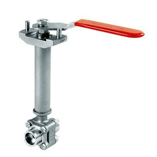
What Are Cryogenic Ball Valves?

Cryogenic Ball Valve
Cryogenic Ball Valve (Flowserve Worcester)
Cryogenic ball valves are high-performance shutoff valves for intermittent and continuous flow applications with temperatures to -425°F. They are used on tough applications involving all types of cryogens, such as oxygen, hydrogen, methane, ammonia, nitrogen, fluorine, LNG and deuterium.

Cryogenic ball valves include unique features to ensure safety and performance in cryogenic applications. Central to the cryogenic design is a rugged, one-piece, pressure safe stem with a Polyfill thrust bearing and stainless steel split ring. It provides design safety and low operational torque. Polyfill seats give you tight shutoff throughout the temperature range. With an orientation-controlled stem/ball connection and an upstream hole in the ball, you get positive overpressure protection.

Summary of specialized design features:
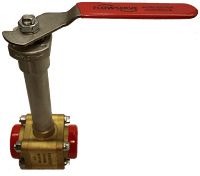
Brass Cryogenic Ball Valve
(Flowserve Worcester)
  • Positive Ball Cavity Relief – An upstream relief hole in the ball prevents dangerous overpressure due to thermal expansion. On extended stem valves through 2", a one-piece stem with alignment pin assures proper orientation of the ball.
  • Pressure Safe Stem – Both one-piece and two-piece, assembled inside-the-body stems are safe from blowout and are supported with Polyfill® thrust washers.
  • Zero Leak Packing – Belleville live-loaded TFE packing rings and stem centering followers assure zero leakage through the toughest, high-cycle applications.
  • Effective Bonnet Extensions – The stem extensions of cryogenic valves conform to standard industrial practices. That means wall thickness and lengths that keep heat transfer down, the packing frost-free, operational torques low, and actuators solidly supported.
  • High-Performance/Low-Thermal Stress – The special “part compatibility” design of valve parts, Polyfill seats and body seals assure tight shutoff, zero body leakage and low torque through large thermal excursions from ambient to -425°F.
Cryogenic valves are normally available in four body configuration, in either stainless steel or brass:
  1. Three-piece construction - makes it easy to install, versatile in application and simple to maintain.
  2. The cryogenic diverter valve - accepts media through the bottom inlet port and directs it to one of two side ports.
  3. The wafer design - a flangeless cryogenic valve that mounts between ANSI Class 150 or 300 flanges.
  4. A flanged design - has a body cast with ANSI Class 150 flanges.
Application for cryogenic ball valves:
  • Over-the-Road LNG-LPG Trailers
  • Terminal Unloading Stations
  • High-Purity Cryogenic/Gas Systems
  • LNG Storage and Distribution
  • CO2 and Nitrogen Injection for Enhanced Oil Recovery
  • Over-the-Road CO2, LNG, Food Carriers
  • Petroleum Refining Unleaded Gasoline (Gas Treatment Skids)
  • Lyophilization Systems
  • Air Separation Plants
  • Liquid and Gaseous Oxygen
  • Inerting and Heat Treatment
For more information on cryogenic ball valves, contact Swanson Flo by visiting https://swansonflo.com or by calling 800-288-7926.

What Are Valve Positioners?

Digital Positioner
Digital Positioner (Valtek)
A valve positioner is used in combination with a valve actuator to precisely position a valve so that optimum flow accuracy may be achieved. The positioner does this by measuring a the process variable, comparing it to a desired condition (set point) and then pneumatically, electrically, or hydraulically changing the valve disc, globe, plug or ball position until the difference between the set point and actual position is zero.

Valve positioners are key elements in a closed loop control system where the final control element is a valve. They assist in maintaining tight control, overcoming the realities of imprecise calibration, differential pressure across the valve, valve wear and a host of other process control challenges.

A valve positioner responds to a signal from some type of master control system, typically a distributed control system (DCS), a programmable logic controller (PLC), or PID controller. The control system reads a signal from a process sensor (flowmeter, temperature sensor, pressure sensor, etc...) and compares that reading to the desired setpoint. A corrective signal, based on the difference,  is provided to the valve positioner which re-adjusts (if necessary) the valve position to bring the system in to equilibrium.

Valve positioners are available with pneumatic, electrical, electro-pneumatic, and digital operation. Here is a brief description of each:

Pneumatic
Pneumatic Positioner
Pneumatic Positioner (Valtek)
Pneumatic positioners receive pneumatic signals (3-15 or 6-30 PSIG). The positioner then throttles supply air to the valve actuator to move the valve to the required position. Pneumatic positioners are intrinsically safe and can provide a large amount of force to close a valve.

Electric
Electric valve positioners receive an electric signal, usually 4-20 mA, 1-5 VDC, 2-10 VCD or 0-10 VDC and generally drive the motors in electric actuators. They perform the same function as pneumatic positioners do, but use electricity instead of air pressure as an input signal.

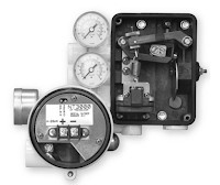
Electro-Pneumatic
Electro-pneumatic Positioner
(PMV)
Electro-pneumatic valve positioners contain internal I/P (current to pneumatic) modules that converts the electrical input signal to a pneumatic output (4-20 mA to 3-15 PSIG for instance). Very similar to a pneumatic positioner except that its input is electrical.

Valve positioners are used throughout the process industries including power, pharmaceutical, chemicals, oil and gas, food and beverage, pulp and paper, refining and petrochemicals, pipelines, and many other processes.

For more information on valve positioners, contact Swanson Flo by visiting https://swansonflo.com or by calling 800-288-7926.

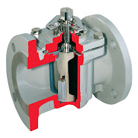
A Process Industry Stalwart - The Plug Valve

Flowserve Durco lubricated plug valve
Lubricated plug valve.
(Flowserve Durco)
This article will focus on one of the oldest and most reliable (when properly applied) industrial valve types - the plug valve.

Fluid process control operations commonly employ pumps, piping, tanks and valves as the means of transporting, containing and controlling the fluid movement through a system.

Valves, of which there are many types, provide control over the flow rate, direction and routing of fluids in a processing operation. Flow can be started, stopped or modulated between zero and full rate using a properly sized and configured valve. Some valves enable media flow to be diverted to a selection of outlets, in lieu of a single inlet and outlet pair. Specialized valves regulate inlet or outlet pressure, or prevent fluid flow from going in an undesirable direction. All of these capabilities are packaged into differing valve product offerings that present a very large selection array to a process designer or engineer.

Floserve Durco non-lubricated plug valve
Non-lubricated plug valve.
(Flowserve Durco)
Industrial flow control valve types are generally classified according to the structure or arrangement contained within the valve body that provides obstruction to fluid flow. Some of the common types are ball, butterfly, gate, globe, and plug. Surely, there are more valve types, and this article is not intended to list them all. Some of our previous blogs have discussed selection considerations for gate, ball and butterfly valves.

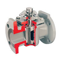
Plug valves, like ball and butterfly valves, span from fully open to fully closed positions with a shaft rotation of 90 degrees. The “plug” in a plug valve is installed in the flow path within the valve body and rotated by means of a stem or shaft extending to the exterior of the body. Plugs are tapered toward the bottom and are fitted to a seating surface in the valve body cavity that prevents fluid from bypassing the plug. An opening through the plug, the port, can be shaped to provide particular flow characteristics. There are two main types of basic plug, lubricated and non-lubricated. Lubricated plug valves have a cavity into which a sealant is injected. The sealant provides a renewable seal between the plug and the body, prevents internal leakage, and protects the seating surfaces against corrosion. Non-lubricated plug valves utilize an elastomeric body liner or a sleeve in the body cavity that is pressed in to the body of the valve by the plug's wedge-like shape,  with the result of reducing the friction between the plug and the body.

Plug valve considerations:
  • 90 degree rotation from open to closed provides fast operation.
  • With proper configuration, can be well suited for frequent operation.
  • Availability of corrosion resistant liner may provide comparative cost savings because valve body can be constructed of less expensive material.
  • Design is simple and employs a low parts count.
  • Valve can be serviced in place.
  • Generally, low resistance to flow when fully open.
  • Reliable leak-tight service due to tapered plug wedging action, replaceable sleeve, and injection of lubricant in some variants.
  • Potential issues of concern for plug valve application include a short list of items.
  • Higher friction in the plug closure mechanism may require comparatively higher operating torque than other valve types.
  • Without a specially designed plug, generally not well suited for throttling applications.
  • Rapid shutoff delivered by plug design may not be suitable for some applications where hammering may occur.
Share your fluid control application challenges with a valve and automation specialist. Leverage your own knowledge and experience with their product application expertise to develop an effective solution.

A Peek Inside a Valtek Mark One Control Valve with Piston Actuator

Valtek Mark One Control ValveThe video below provides a look inside the Flowserve Valtek Mark One control valve and identifies its major components.

The Flowserve Valtek® Mark One globe control valve is designed for liquid and gaseous services, and for permitting easy, fast and inexpensive maintenance.

The spring-cylinder actuated Mark One valve provides stiffness and maintains high positioning accuracy, repeatability, controlled high speed, and faithful response. The Mark One valve handles up to 150 psig supply air and has the thrust to shut off against much higher fluid pressures.

The Mark One valve is designed so the spring, supply air pressure and fluid pressure itself combine to produce exceptionally tight shutoff. A self-aligning seat ring further enhances the shutoff capability of the valve.

https://swansonflo.com
800-288-7926

Limitorque MX Actuator Users Instructions, Maintenance, and Spare Parts Manual

Flowserve Limitorque MX
The Flowserve Limitorque MX actuator controls the opening and closing travel of valves and other actuated devices. OPEN and CLOSED limits are protected by an absolute encoder that provides optical sensing of valve position and measures valve position in both motor and handwheel operation.

No battery or backup power supply is required. Output torque is derived from motor speed, temperature, and voltage. If the preset torque is exceeded, the motor shuts off. As a result of this reliable and advanced protection technology, all valve and other actuated devices are protected from potential damage from overload, improper seating, and foreign obstructions.

A range of control and network options is available and can be easily added to the control capabilities already available on a standard actuator.

You can download the Limitorque MX Electronic Actuator User Instructions, Maintenance, and Spare Parts Manual in PDF version from the Swanson Flo site here (8.5MB), or read the embedded version below.

Flowserve Valtek MaxFlo 4 Eccentric Rotary Plug Control Valve

Valtek MaxFlo 4 Eccentric Rotary Plug Control Valve
The Flowserve Valtek MaxFlo 4 control valve is a high performance eccentric rotary plug valve designed for the process industry. It features a large capacity, standard hardened trim and superior shaft blow-out protection.

This valve is available in sizes 1 through 12 inches, ASME Class 150, 300 and 600 as well as DIN PN 10, PN16, PN 25, PN40 and PN63. An optional ISA 75.08.01 or DIN EN 558 series 1 long-pattern body makes this valve an easy drop-in replacement for a globe control valve. 

Founded in 1960, Swanson Flo has long maintained our position as an industry leader in process automation with unmatched project success leveraging industry preferred products and services. 

800-288-7926

Understanding Linear, Equal Percentage, and Quick Open Control Valve Flow Curves

Flowserve Valtek Control Valve
Flow characteristics, the relationship between flow coefficient and valve stroke, has been a subject of considerable debate. Many valve types, such as butterfly, eccentric disk and ball valves, have an inherent characteristic which cannot be changed (except with characterizable positioner cams). Flow characteristics of globe valves can be determined by the shape of the plug head.

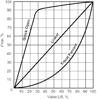
The three most common types of flow characteristics are quick opening, equal percentage and linear. The figure below shows the ideal characteristic curve for each. These characteristics can be approximated by contouring the plug. However, inasmuch as there are body effects and other uncontrollable factors, plus the need for maximizing the flow capacity for a particular valve, the real curves often deviate considerably from these ideals. When a constant pressure drop is maintained across the valve, the characteristic of the valve alone controls the flow; this characteristic is referred to as the “inherent flow characteristic.” “Installed characteristics” include both the valve and pipeline effects. The difference can best be understood by examining an entire system.

Equal Percentage
Control valve flow curves
Control valve flow curves.


Equal percentage is the characteristic most commonly used in process control. The change in flow per unit of valve stroke is directly proportional to the flow occurring just before the change is made. While the flow characteristic of the valve itself may be equal percentage, most control loops will produce an installed characteristic approaching linear when the overall system pressure drop is large relative to that across the valve.

Linear

An inherently linear characteristic produces equal changes in flow per unit of valve stroke regardless of plug position. Linear plugs are used on those systems where the valve pressure drop is a major portion of the total system pressure drop.

Quick Open

Quick open plugs are used for on-off applications designed to produce maximum flow quickly.

This information provided courtesy of Flowserve Valtek. Share your control valve requirements and challenges with a valve specialist, combining your own process knowledge and experience with their product application expertise to develop effective solutions.

Lined Industrial Valves for Corrosive Service

Lined Durco Plug Valves
Lined Plug Valves
(courtesy of Flowserve Durco)
Lined valves use a fluoropolymer, plastic, or ceramic lining applied to all wetted internal parts of the valve.

Lined valves combine the excellent mechanical properties of metallic bodies with the corrosion resistance of fluorocarbons, such as PFA and PTFE.

Lining the intricately shaped inside surfaces of a valve is certainly an engineering challenge, especially to achieve a uniform thickness and the highest lining quality, without cavities or inclusions.

Lined Valves
Lined ball and swing check valve
(courtesy of Flowserve Atomac)
The special lining process guarantees tight bonding between the lining and the inside of the body.
This effectively prevents the lining from shearing off the body in part or being removed completely.

Ideal applications include highly corrosive applications within the chemical processing industry such as sulfuric and hydrochloric acid.

Lined valves are ideally suited for corrosive applications, requiring very reliable performance, tight shutoff, constant torque and no maintenance. These valves have gained extensive usage in many industries including power generation, pulp and paper, refineries, chemical process, pharmaceutical/bioprocessing and pollution control.

For more information on lined valves, visit Swanson Flo at http://www.swansonflo.com or call 800-288-7926.

Flowserve Valtek Valve Automation

The video below highlights several Swanson Flo automated Valtek control valves. Included in these systems are Valtek ShearStream segmented ball valves, Valtek Valdisk BX butterfly valves, Logix positioners, Valtek VR piston actuators, and StoneL Axiom valve monitors.


Swanson Flo is a premier valve and valve automation supplier located in Plymouth, MN with warehouse and fabrication facilities in Addison, IL, Indianapolis, IN and Menomonee Falls, WI.

Visit Swanson Flo at http://www.swansonflo.com or call 800-288-7926 with any valve automation project.

Understanding Control Valves: The Flowserve Valtek Mark One

Control valves are an integral part of many process control loops. Understanding their basic operation is important for any process control professional. The following video demonstrates the reassembly of the Flowserve Valtek Mark One control valve and introduces the viewer to a control valve's main components.

There are a variety of styles of control valves. A globe control valve is a specific type of valve used for regulating flow in a pipe. The design includes a movable plug, connected to a stem, which can be moved linearly to close or open the valve. Globe control valves are referred to as “linear” valves because of this movement to open and close is directed by a piston type, linear movement actuator. Generally, globe control valves provide better overall flow control than quarter-turn valves due to the design of their flow path.

For more information, a Valtek Mark One specification sheet is also included with this post.