Patented Pressure Gauge Technology Eliminates Need for Liquid Fills

Pulsating gauge
Pulsations caused by compressors and other machinery.
Patented technology by Ashcroft dampen pulsations
without the cost and hassle of liquid-fill.
Compressors pumps and other machinery create pulsation and vibration that can make your pointer unreadable.  Liquid-filled gauges can solve your problem, but they command a higher price.  So to keep costs down, you have to stock both dry and liquid-fill gauges.

In response, Ashcroft developed their patented PLUS!™ Performance technology. Gauges with PLUS!™ Performance employ a unique cartridge that surrounds the pinion with an engineered dampening medium. This viscous compound encapsulates and stabilizes the pinion in order to restrict the overactive pointer motion due to vibration. A throttle screw helps to neutralize pulsation by restricting the flow rate of the pressure medium into the Bourdon tube.


Plus! technology
Pinion is stabilized by a cartridge with viscous compound.
While a standard dry gauge may become indecipherable, both liquid-filled and PLUS!™ Performance gauges continue to provide stable readings.  the liquid fill can leak, be affected by extreme ambient temperatures, and become an environmental hazard when disposed of. Ashcroft's patented PLUS!™ Performance option assures fast and easy readings so you can focus on what matters and standardizing with PLUS!™ Performance helps consolidate your SKUs, and less inventory means lower costs.

For more information, contact Swanson Flo by calling 800-288-7926 or visit their web site at https://swansonflo.com.

The Valtek® Mark Eight™ Y-Pattern Control Valve

Mark Eight Control Valve
The Valtek Mark Eight Control Valve Features
(Click for larger view)
The Valtek® Mark Eight™ control valve is designed with a unique “Y” style globe body that provides higher flow capacities and less process turbulence than conventional globe valves.

Because of its nearly straight-through flow passage, the “Y” style body is less flow restrictive than a normal globe-style body. This permits less pressure to be converted into velocity as the fluid passes through the seat, resulting in a lower valve recovery factor and higher capacity.

Mark Eight’s straight-through design generates less valve and piping turbulence which significantly reduces harmful noise and vibration levels.


Applying Gas Pipeline Block Station Valves


A block valve is used on gas transmission systems to isolate a segment of the main gas pipeline for inspection and maintenance, or for shutdown in the case of a natural disaster or pipeline damage.

The block valve is typically a full-bore, soft seated ball valve to allow for scraping. However, this type of valve cannot be opened against full differential pressure without damage to the valve seats. Therefore, a bypass system is installed around the block valve, and used to balance the pipeline pressure prior to opening. Plug valves should be used in the bypass as they are capable of opening and throttling against full differential pressure without damage.

The Requirement of a Bypass

Let's see what would happen if the block valve, which is a soft seated ball valve, was operated against full differential pressure. As it is initially opened the huge pressure drop across the valve generates high velocity flow carrying fine dust, rust, or scale particles in close proximity of the valve seats. This results in seat damage and a block valve that cannot seal bubble tight once closed.

The Bypass Valve Sequence

To avoid this, a bypass system is utilized to balance the pressure either side of the block valve prior to opening it. With the vent valve closed, bypass valve 1 is opened allowing pressure into the bypass. In this case, a plug valve should be used, as it can be opened against full differential pressure without seat damage. Now bypass valve 2 is slowly opened, gradually building pressure in the downstream section until the pressure either side of the block valve is equalized. A plug valve is also used here capable of throttling the flow without seat damaged. With the pressure now equalized the block valve can be opened safely without the risk of seat damage. The two bypass valves have now done their job and can be closed providing bubble tight shutoff against the main pipeline.

Venting a Pipeline Section

Block stations are also used to vent sections of the pipeline into the atmosphere. This operation would start with all valves in the closed position. Bypass valve 1 is then opened allowing pressure into the bypass station. The vent valve is now slowly opened to release the pipeline pressure. Once again, this is a demanding application opening against full differential pressure, hence a plug valve is used to ensure bubble tight isolation to the atmosphere once closed.

For more information, contact Swanson Flo by visiting https://swansonflow.com or by calling 800-288-7926.

US Power Grids, Oil and Gas Industries, and Risk of Hacking

A report released in June, from the security firm Dragos, describes a worrisome development by a hacker group named, “Xenotime” and at least two dangerous oil and gas intrusions and ongoing reconnaissance on United States power grids.

Multiple ICS (Industrial Control Sectors) sectors now face the XENOTIME threat; this means individual verticals – such as oil and gas, manufacturing, or electric – cannot ignore threats to other ICS entities because they are not specifically targeted.


The Dragos researchers have termed this threat proliferation as the world’s most dangerous cyberthreat since an event in 2017 where Xenotime had caused a serious operational outage at a crucial site in the Middle East. 

The fact that concerns cybersecurity experts the most is that this hacking attack was a malware that chose to target the facility safety processes (SIS – safety instrumentation system).

For example, when temperatures in a reactor increase to an unsafe level, an SIS will automatically start a cooling process or immediately close a valve to prevent a safety accident. The SIS safety stems are both hardware and software that combine to protect facilities from life threatening accidents.

At this point, no one is sure who is behind Xenotime. Russia has been connected to one of the critical infrastructure attacks in the Ukraine.  That attack was viewed to be the first hacker related power grid outage.

This is a “Cause for Concern” post that was published by Dragos on June 14, 2019

“While none of the electric utility targeting events has resulted in a known, successful intrusion into victim organizations to date, the persistent attempts, and expansion in scope is cause for definite concern. XENOTIME has successfully compromised several oil and gas environments which demonstrates its ability to do so in other verticals. Specifically, XENOTIME remains one of only four threats (along with ELECTRUM, Sandworm, and the entities responsible for Stuxnet) to execute a deliberate disruptive or destructive attack.

XENOTIME is the only known entity to specifically target safety instrumented systems (SIS) for disruptive or destructive purposes. Electric utility environments are significantly different from oil and gas operations in several aspects, but electric operations still have safety and protection equipment that could be targeted with similar tradecraft. XENOTIME expressing consistent, direct interest in electric utility operations is a cause for deep concern given this adversary’s willingness to compromise process safety – and thus integrity – to fulfill its mission.

XENOTIME’s expansion to another industry vertical is emblematic of an increasingly hostile industrial threat landscape. Most observed XENOTIME activity focuses on initial information gathering and access operations necessary for follow-on ICS intrusion operations. As seen in long-running state-sponsored intrusions into US, UK, and other electric infrastructure, entities are increasingly interested in the fundamentals of ICS operations and displaying all the hallmarks associated with information and access acquisition necessary to conduct future attacks. While Dragos sees no evidence at this time indicating that XENOTIME (or any other activity group, such as ELECTRUM or ALLANITE) is capable of executing a prolonged disruptive or destructive event on electric utility operations, observed activity strongly signals adversary interest in meeting the prerequisites for doing so.”

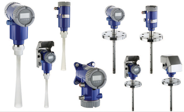
Guided Wave Radar Transmitters: Accurate and Reliable Level Measurement for the Widest Choice of Installation Options and Applications

guided wave radar level

Guided wave radar transmitters are widely used across different industries. These devices with their simple installation and trouble-free operations help industrial companies save time and money. They are ideal for a large number of process applications ranging from simple to complex.

How Do Guided Wave Radar Transmitters Work?


Guided wave radar transmitters rely on microwave pulses. Since microwaves are not affected by dust, pressure, temperature variations, and viscosity, this type of transmitter produces highly accurate results. 

A low-energy microwave pulse is sent down a probe, and a part of it is reflected back when the pulse hits the process media. The liquid level is directly proportional to the time-domain reflectometry. The time when the pulse is launched and received back is measured to determine the distance from the surface of the media. 

Types of Guided Wave Radar Level Transmitters


Guided wave radar level transmitters are available in different probe configurations. Selecting the right probe is important for successful implementation of the device. While manufacturers offer a range of guided wave radars, most are derived from the three basic probe configurations: single element, twin element, and coaxial.

Single element probe — The single element probe is the most widely used and least efficient device. The device is popular since it is more resistant to the coating of the liquid. 

Twin element probe — The twin element probe is a good, general purpose probe that is generally used in long-range applications. They are ideal in situations where flexible probes are important for successful reading. 

Coaxial probe — The coaxial probe configuration is the most efficient guided wave radar level transmitters. The probes are used in more challenging low-dielectric applications. 

Benefits of Guided Wave Radar Level Transmitters


Dielectric Constant and Reflectivity - Guided WaveRadar (GWR)
(Courtesy of Schneider Electric Foxboro)
Guided wave radar level transmitters provide a range of benefits in different applications. The concentration of the measuring signal is strong and clean. This is due to the narrow path of the signal propagation that reduces the chances of impact by stray signals due to obstacles or construction elements inside the tank. 

Another benefit of guided wave radar level transmitters is that they are easy to install. No mounting holes are required to install the device. This results in cost savings for the organization. The waveguide can be formed to follow the tank’s contours or mounted at an angle. 

The device is ideal in situations where an interface measurement is required. The measuring signals can penetrate the medium deeply, resulting in more accurate results. The waveguide technology is suitable for applications where the medium is subjected to heavy vapors, foam, and dust. 

Guided wave instruments can detect changes in dielectric consents on the boundary of a property. The device can be configured to detect level at both the top and the bottom of a layer of emulsion. 

Industrial Application of Guided Wave Radar


Guided wave radar level transmitters are increasingly being used in process industries. The sensors are used in situations that previously employed ultrasonic, hydrostatics, and capacitance. The accuracy specification of the basic model range is up to ±5mm, while the accuracy of the advanced models is up to ±2mm. 

The device is generally used in industries to take level readings. The readings are used for local indication and visualization in control systems. 

Moreover, guided wave radar level transmitters are also used for managing liquid inventory, determining safety limits, dry run protection, and leak detection. Other applications of guided wave radar level transmitters include communicating low limits to suppliers, automated ordering systems, and streamlining the logistics process. 

Guided radar level measurement is also suitable for bulk solids. The surface type is not restricted to liquids since the reflected waves are guided easily through any medium. Foam formation and turbulent liquid surfaces and different angled surfaces (as is the case with bulk solids) don’t influence the accuracy of the reading.

Selection of Guided Wave Radar Level Transmitters


Selection of guided wave radar level transmitters should be based on the requirements of the task. Generally, the rigid single element probe configuration is ideal for angled installations for flowing liquids. The dual flexible wire probe is suitable for most other common applications. 

A coaxial probe configuration is recommended for liquids that are cleaner with low dielectric constant and with turbulence on the product’s surface. This type of guided wave radar device is also recommended for installations where the probe is near the tank wall or other obstacles. 

Make sure that the device can withstand the range of temperature within the tank. Most GWR devices are rated up to 850 deg F or 450 deg C. You should select a device with added signal strength since this will result in increased reliability and accuracy of the devices. 

Guided wave radar level transmitter with dynamic vapor compensation is recommended where a high level of accuracy is required under a high-pressure environment. The measurement taken from the device can compensate for changes in vapor dielectric, which results in improved accuracy. 

Other factors that should be considered include mounting and proximity. Single probe configuration can be installed almost anywhere. But the single probe configuration can only to apply to specific situations. 

Lastly, the probe length of the device should be of the right length. The length should be according to the measurement rate. This is an important consideration as it can help in ensuring accurate reading with minimum chances of an error. 

Guided wave radar level transmitters can also be used with an agitator. However, certain things must be considered prior to use the device. The probe must be prevented from contacting the agitator blades. Make sure that you confirm the ability of the probe to withstand the force inside the medium. This is important since turbulent on the surface may decrease the accuracy of the measurement. You can install the device in a bypass chamber or stilling well for an agitated tank.

For more information on guided wave level transmitters, contact Swanson Flo by calling 800-288-7926 or by visiting their web site at https://swansonflo.com.

Hazardous Area Classifications in the USA

Hazardous Area Classifications
Understanding Hazardous Area classifications is critical.
An important aspect of safe installation is to determine the hazardous area classification in the area. Checking the area classification is also important for safe electrical wiring. The hazardous area classification should be known by personnel before starting work in an area.

Hazardous areas refer to locations with a possible risk of explosion or fire due to dangerous atmosphere. The hazards can be associated with flammable vapors or gases, ignitable fibers, and combustible dusts.

Different hazardous area classifications exist in the North America and Europe. Generally, the National Electric Code (NEC) classifications govern hazardous areas in the US. While in Europe, hazardous area classification has been specified by the International Electrotechnical Commission (IEC).

CLASS
NATURE OF HAZARDOUS MATERIAL
CLASS I
Hazardous area due the presence of flammable vapors or gases in sufficient quantities to produce ignitable mixtures and cause an explosion.
Examples include natural gas and liquified petroleum.
CLASS II
Hazardous area due the presence of conductive or combustible dusts in sufficient quantities to produce ignitable mixtures and cause an explosion.
Examples include aluminum and magnesium powders.
CLASS III
Hazardous area due the presence of flammable fibers or other flying debris that collect around lighting fixtures, machinery, and other areas in sufficient quantities to produce ignitable mixtures and cause an explosion.
Examples include sawdust and flyings


Division groups hazardous areas based on the chances of an explosion due to the presence of flammable materials in the area.

DIVISION
LIKELIHOOD OF HAZARDOUS MATERIAL
DIVISION 1
Areas where there is a high chance of an explosion due to hazardous material that is present periodically, intermittently, or continuously under normal operation.
DIVISION 2
Areas where there is a low chance of an explosion under normal operation.


Group categorizes areas based on the type of flammable or ignitable materials in the environment. As per NEC guidelines, Groups A to D classify gasses while Groups E to G classify dust and flying debris.
GROUP
TYPE OF HAZARDOUS MATERIAL IN THE AREA
GROUP A
Acetylene.
GROUP B
Area contains flammable gas, liquid, or liquid produced vapor with any of the following characteristics:
  • Minimum Ignition Current (MIC) value equal to or less than 0.40
  • Maximum Experimental Safe Gap (MESG) value equal to or less than 0.45 mm
  • Combustible gas with more than 30 percent volume
Examples include hydrogen, ethylene oxide, acrolein, propylene oxide.

GROUP C
Area contains flammable gas, liquid, or liquid produced vapor with any of the following characteristics:
  • Minimum Ignition Current (MIC) value between 0.40 and 0.80
  • Maximum Experimental Safe Gap (MESG) value greater than 0.75 mm
Examples include carbon monoxide, hydrogen sulphide, ether, cyclopropane, morphline, acetaldehyde, isoprene, and ethylene.

GROUP D
Area contains flammable gas, liquid, or liquid produced vapor with any of the following characteristics:
  • Minimum Ignition Current (MIC) value greater than 0.80
  • Maximum Experimental Safe Gap (MESG) value greater than 0.75 mm
Examples include ammonia, gasoline, butane, benzene, hexane, ethanol, methane, methanol, natural gas, propane, naphtha, and vinyl chloride.

GROUP E
Area contains metal dusts such as magnesium, aluminum, chromium, bronze, titanium, zinc, and other combustible dusts whose abrasiveness, size, and conductivity present a hazard.

GROUP F
Area contains carbonaceous dusts such as charcoal, coal black, carbon black, coke dusts and others that present an explosion hazard.
GROUP G
Area contains combustible dusts not classified in Groups E and F.
Examples include starch, grain, flour, wood, plastic, sugar, and chemicals.


NOTE: This post serves only as a guide to acquaint the reader with hazardous area classifications in the USA. It is imperative to discuss your instrumentation, valve, or process equipment requirement with a qualified applications expert prior to installing any electrical device inside of any hazardous area.

800-288-7926