Showing posts with label process control. Show all posts

Fractional Flow Control Valves from Swanson Flo

Mark 708

For Critical Fractional Flow Control of Liquid, Gas, or Steam


LowFlow control valves have applications in OEM, laboratory, and pilot plant applications. Installations such as these frequently require valve trim changes to meet varying flow requirements for a given application. Monel,  Hastelloy, Alloy 20, Titanium, Kynar, and Inconel are just a few of the materials LowFlow offers to address your material compatibility challenges.

LowFlow control valves require no special tools for trim changes. Their bolted body design means you don’t even have to take the valve out of line for trim changes or maintenance.

LowFlow Valve provides products across an incredibly diverse range of industries and applications, from operating in cryogenic applications down to -425°F (-254°C)  to temperatures above 1000°F (538°C).

The Mark 708 valve provides accurate control on fractional flow applications. It is a complete line of pneumatic and electrically actuated control valves designed to enhance performance to ensure precision control on your most critical microflow applications. 

Swanson Flo is your low flow control valve and instrumentation expert. Call us with any challenging low flow application, and our engineers will be pleased to assist you. Call 800-288-7926 or visit https://swansonflo.com.

Hazardous Area Classifications in the USA

Hazardous Area Classifications
Understanding Hazardous Area classifications is critical.
An important aspect of safe installation is to determine the hazardous area classification in the area. Checking the area classification is also important for safe electrical wiring. The hazardous area classification should be known by personnel before starting work in an area.

Hazardous areas refer to locations with a possible risk of explosion or fire due to dangerous atmosphere. The hazards can be associated with flammable vapors or gases, ignitable fibers, and combustible dusts.

Different hazardous area classifications exist in the North America and Europe. Generally, the National Electric Code (NEC) classifications govern hazardous areas in the US. While in Europe, hazardous area classification has been specified by the International Electrotechnical Commission (IEC).

CLASS
NATURE OF HAZARDOUS MATERIAL
CLASS I
Hazardous area due the presence of flammable vapors or gases in sufficient quantities to produce ignitable mixtures and cause an explosion.
Examples include natural gas and liquified petroleum.
CLASS II
Hazardous area due the presence of conductive or combustible dusts in sufficient quantities to produce ignitable mixtures and cause an explosion.
Examples include aluminum and magnesium powders.
CLASS III
Hazardous area due the presence of flammable fibers or other flying debris that collect around lighting fixtures, machinery, and other areas in sufficient quantities to produce ignitable mixtures and cause an explosion.
Examples include sawdust and flyings


Division groups hazardous areas based on the chances of an explosion due to the presence of flammable materials in the area.

DIVISION
LIKELIHOOD OF HAZARDOUS MATERIAL
DIVISION 1
Areas where there is a high chance of an explosion due to hazardous material that is present periodically, intermittently, or continuously under normal operation.
DIVISION 2
Areas where there is a low chance of an explosion under normal operation.


Group categorizes areas based on the type of flammable or ignitable materials in the environment. As per NEC guidelines, Groups A to D classify gasses while Groups E to G classify dust and flying debris.
GROUP
TYPE OF HAZARDOUS MATERIAL IN THE AREA
GROUP A
Acetylene.
GROUP B
Area contains flammable gas, liquid, or liquid produced vapor with any of the following characteristics:
  • Minimum Ignition Current (MIC) value equal to or less than 0.40
  • Maximum Experimental Safe Gap (MESG) value equal to or less than 0.45 mm
  • Combustible gas with more than 30 percent volume
Examples include hydrogen, ethylene oxide, acrolein, propylene oxide.

GROUP C
Area contains flammable gas, liquid, or liquid produced vapor with any of the following characteristics:
  • Minimum Ignition Current (MIC) value between 0.40 and 0.80
  • Maximum Experimental Safe Gap (MESG) value greater than 0.75 mm
Examples include carbon monoxide, hydrogen sulphide, ether, cyclopropane, morphline, acetaldehyde, isoprene, and ethylene.

GROUP D
Area contains flammable gas, liquid, or liquid produced vapor with any of the following characteristics:
  • Minimum Ignition Current (MIC) value greater than 0.80
  • Maximum Experimental Safe Gap (MESG) value greater than 0.75 mm
Examples include ammonia, gasoline, butane, benzene, hexane, ethanol, methane, methanol, natural gas, propane, naphtha, and vinyl chloride.

GROUP E
Area contains metal dusts such as magnesium, aluminum, chromium, bronze, titanium, zinc, and other combustible dusts whose abrasiveness, size, and conductivity present a hazard.

GROUP F
Area contains carbonaceous dusts such as charcoal, coal black, carbon black, coke dusts and others that present an explosion hazard.
GROUP G
Area contains combustible dusts not classified in Groups E and F.
Examples include starch, grain, flour, wood, plastic, sugar, and chemicals.


NOTE: This post serves only as a guide to acquaint the reader with hazardous area classifications in the USA. It is imperative to discuss your instrumentation, valve, or process equipment requirement with a qualified applications expert prior to installing any electrical device inside of any hazardous area.

800-288-7926 

Wireless Networking in Industrial Plants

Wireless Networking in Industrial Plants
Wireless networking serves as the ideal alternative to high-cost industrial wiring. The setup also provides superior performance, solving the problem of electrical surges that result from field wiring.

Using a wireless system can result in an efficient supply of networking resources to field devices. The system facilitates an effective exchange of data between the host server and the field devices in the industrial setting.

Only a few industry-grade wireless field sensors have been offered so far in the year 2019. The reason for this is mainly a lack of information regarding its benefits. Once the cost-saving aspects of wireless networking become known in the industrial setting, it will likely spur the demand in the market and lead to an influx of innovative wireless devices for different field applications.

Benefits of Wireless Networking Systems in the Industrial Setting Explored 

Wireless technologies offer great value over wired solutions. A reduction in cost is just one of the many benefits of switching to the wireless networking system. There are many benefits, including enhanced management of legacy systems that were previously not possible with a wired networking connection.

Here is an overview of some of the value-added benefits of adopting wireless networking in industrial plants.

Reduced Installation Costs 

Savings in installation costs is the key benefit of a wireless networking system. The cost of installing a wireless solution is significantly lower as compared to its wired counterpart.

Installing a wireless network requires less planning. Extensive surveys are not required to route the wires to control rooms. This reduced installation cost is the main reason industrial setups should consider going wireless instead of having a wired networking system.

Improved Information Accuracy 

Adopting wireless networking also results in improved accuracy of information. The wireless system is not prone to interferences. As a result, the system ensures consistent and timely transfer of information from one node to another.

Enhanced Flexibility 

Enhanced flexibility is another reason for deploying wireless networking solutions in an industrial setting. Additional points can be awarded easily in an incremental manner. The wireless system can also integrate with legacy systems without any issues.

Operational Efficiencies

Migrating to wireless networking can help in improving operational efficiencies as well. Plant managers can troubleshoot and diagnose issues more easily. The system facilitates predictive maintenance by allowing the monitoring of remote assets.

Human Safety 

Another critical factor that should influence the decision to migrate to wireless networking is the human safety factor. Wireless technologies allow safer operations, reducing exposure to harmful environments. For instance, a wireless system can be used in taking a reading and adjusting valves without having to go to the problematic area to take measurements.

Efficient Information Transfer

Another advantage is that the time required to reach a device is reduced. This results in a more efficient transfer of information between network segments that are geographically separated. The industry wireless networking standards use IP addresses to allow remote access to data from field devices.

With wireless networking systems, readings can be taken more frequently that can help in early detection and reduction of possible incidents.

Wireless Networking Standards for Industrial Plants

The ISO100 standards committee has introduced a whole set of new standards for wireless communication in industries. The first standards include the ISA100.11 that pertains to processing data transfer while fulfilling limited control needs in the industries.

Wireless Networking in Industrial Plants
Hybrid architecture using WirelessHART mesh networking coupled
with ultra-efficient BLE Instrument Area Networks.
Image courtesy of Foxboro Schneider Electric.
ANSI and ISA have adopted the ISA100.11a standards for wireless communication in process industries. However, the standard has yet to pass through the international IEC standardization. This is due to the fact that ISA100.11a and IEC’s WirelessHART standards address the same market.

Technical Basis 

ISA100.11a is based on IEEE 802.15.4:2006 standard, similar to WirelessHART with 15 to 16 channels in the ISM band 2.4GHz range. However, the former can be used for a wider networking application in the industrial sector such as peer-to-peer messaging and network segmentation.

Distinct Hopping Patterns

Each segment in the network may use a distinct hopping pattern, unlike the WirelessHART. Moreover, the network segment has a dedicated time slot that results in the formation of large networks with overlapping segments.

Mesh Networking 

Another important point to note is that the ISA1001.11a wireless networking standard for industrial process makes use of mesh networking, which is similar to WirelessHART. However, the standard also allows devices at the network’s edge to not route information to different devices. This results in increased security that prevents unauthorized access to networks.

While not being technically different, the details of the two standards set them apart. However, the IS100.12 is already in development, and it will reduce the divergence in specifications between WirelessHART and ISA100.11a.

Challenges in Adopting Industrial Wireless Networking

Industrial wireless communication technology is a work in progress. A lot of work is required to address specific technical challenges for adopting the networking solution. Some of the challenges include evaluation and communication of the wireless technologies that are available for industrial concerns.

Another challenge in the adoption of wireless technology is solving the issues of latency or time synchronization. This is important to ensure the reliability of data transferred in the industrial setting.

Based on the challenges identified, here are three key suggestions for implementing wireless technology in the industrial setting.

  • Create a science-based methodology for measuring the performance of wireless communication
  • Create guidelines for the deployment of wireless networking in an industrial environment
  • Address issues of latency in systems with high-reliability aspects with error rates less than 10 percent

Key Takeaway

Wireless networking is an enabling technology that can result in improved operational efficiency in the industrial systems. The technology can improve control and safety and lead to enhanced cost savings.

Adoption of the wireless networking system creates huge potential for increased operational efficiencies. The system can reduce installation cost, enable enhanced monitoring, reduce risks, and improve profitability.

For more information on industrial wireless networking, contact Swanson Flo by calling 800-288-7926 or by visiting https://swansonflo.com.

Properties of Fluids: The Basics


This video introduces the viewer to basic fluid properties such as viscosity, viscosity index, compressibility, cleanliness, filtration and additives. These basics apply throughout process control, from flow instrumentation to valve automation.

Founded in 1960, Swanson Flo has long maintained our position as an industry leader in process automation with unmatched project success leveraging industry preferred products and services.

https://swansonflow.com
800-288-792

Flowserve Control Valve Product Guide (Valtek, Kammer)

Flowserve Control Valve
Flowserve general service control valves combine platform standardization, high performance, and simplified maintenance to deliver a lower total cost of ownership.

Flowserve delivers a broad range of general service control valves – linear and rotary – with pressure ratings of ANSI Class 150 to 4500/PN 10 to PN 640. These high-performance control valves offer greater reliability, precision control, and flow capacity, with significantly reduced cavitation, flashing, and noise. Quality production ensures increased process yield and throughput.

Because Flowserve general service control valves are constructed on global platforms using standardized parts and components, up-front engineering is held to a minimum. Simplified operation, maintenance, and service further ensure lower total cost of ownership.

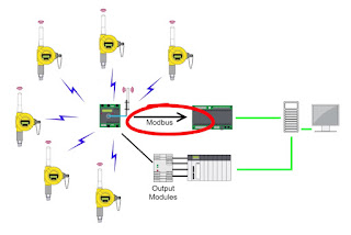
Wireless Process Control Instrumentation

Wireless Process Control Instrumentation
Wireless Process Control Instrumentation Diagram
Manufacturing plants are continually under tremendous pressure with demands for safety, reliability, and efficiency. Unplanned shutdowns and outages have a huge impact effects on plant performance. Lost production, escalating energy costs, unexpected maintenance costs, and heightened safety concerns are the real outcomes of equipment failure. New, developing process technologies must mitigate these plant control realities.

Wireless process control technology is a serious contender in the ongoing effort to improve plant efficiency,  mitigate risk, and increase productivity. Today's wireless transmitters are available for monitoring virtually any process control variable including flow, pressure, level, temperature, pH, Dissolved Oxygen, etc. Very notably, in the harshest environments, these devices reliably transmit critical control data back to central control areas around the clock and without the need for human presence.

The argument for wireless instrumentation is very compelling when you consider installation convenience and cost savings.  Some cost savings estimates run as high as 70%  by eliminating wires and cables, as opposed to the cost when using cables for the same application. And most remarkably, wireless instruments provide additional safety and compliance benefits by keeping maintenance personnel out of dangerous or hazardous areas.

All manufacturing industries are faced with the realities of cost cutting as plant managers endeavor toward continuous process improvement. The need for better solutions is always present, and wireless process instruments certainly appear to fit the bill. But before widespread adaptation of wireless occurs, concerns about reliability, user comfort, and integration must be overcome. However, as plant managers see the downward pressure on deployment and maintenance costs, and as they see improved employee safety and smoother environmental compliance, adoption of wireless instrumentation will accelerate and eventually become ubiquitous in process control.

Understanding Explosion Proof Enclosures Used in Process Control

This is a short video that explains what an explosion-proof enclosure is, what defines it as “explosion-proof”, and the principle behind why its safe to use in explosive or combustible atmospheres.

“Explosion-proof" doesn't mean the enclosure can withstand the forces of an external explosion. It means that the enclosure is designed to cool any escaping hot gases (caused by an internal ignition) sufficiently enough as to prevent the ignition of combustible gases or dusts in the surrounding area.

https://swansonflo.com
800-288-7926

Introduction to Industrial Control Systems

Industrial Control Systems Control systems are computer-based systems that are used by many infrastructures and industries to monitor and control sensitive processes and physical functions. Typically, control systems collect sensor measurements and operational data from the field, process and display this information, and relay control commands to local or remote equipment. In the electric power industry they can manage and control the transmission and delivery of electric power, for example, by opening and closing circuit breakers and setting thresholds for preventive shutdowns. Employing integrated control systems, the oil and gas industry can control the refining operations on a plant site as well as remotely monitor the pressure and flow of gas pipelines and control the flow and pathways of gas transmission. In water utilities, they can remotely monitor well levels and control the wells’ pumps; monitor flows, tank levels, or pressure in storage tanks; monitor water quality characteristics, such as pH, turbidity, and chlorine residual; and control the addition of chemicals. Control system functions vary from simple to complex; they can be used to simply monitor processes—for example, the environmental conditions in a small office building—or manage most activities in a municipal water system or even a nuclear power plant.

Industrial Control SystemsIn certain industries such as chemical and power generation, safety systems are typically implemented to mitigate a disastrous event if control and other systems fail. In addition, to guard against both physical attack and system failure, organizations may establish back-up control centers that include uninterruptible power supplies and backup generators.

There are two primary types of control systems. Distributed Control Systems (DCS) typically are Supervisory Control and Data Acquisition (SCADA) systems typically are used for large, geographically dispersed distribution operations. A utility company may use a DCS to generate power and a SCADA system to distribute it.

process instruments
Field devices and discreet controllers used in control systems
(Foxboro Schneider Electric).
A control system typically consists of a “master” or central supervisory control and monitoring station consisting of one or more human-machine interfaces where an operator can view status information about the remote sites and issue commands directly to the system. Typically, this station is located at a main site along with application servers and an engineering workstation that is used to configure and troubleshoot the other control system components. The supervisory control and monitoring station is typically connected to local controller stations through a hard- wired network or to remote controller stations through a communications network—which could be the Internet, a public switched telephone network, or a cable or wireless (e.g. radio, microwave, or Wi-Fi) network. Each controller station has a Remote Terminal Unit (RTU), a Programmable Logic Controller (PLC), DCS controller, or other controller that communicates with the supervisory control and monitoring station. The controller stations also include sensors and control equipment that connect directly with the working components of the infrastructure—for example, pipelines, water towers, and power lines. The sensor takes readings from the infrastructure equipment—such as water or pressure levels, electrical voltage or current—and sends a message to the controller. The controller may be programmed to determine a course of action and send a message to the control equipment instructing it what to do—for example, to turn off a valve or dispense a chemical. If the controller is not programmed to determine a course of action, the controller communicates with the supervisory control and monitoring station before sending a command back to the control equipment. The control system also can be programmed to issue alarms back to the operator when certain conditions are detected. Handheld devices, such as personal digital assistants, can be used to locally monitor controller stations. Experts report that technologies in controller stations are becoming more intelligent and automated and communicate with the supervisory central monitoring and control station less frequently, requiring less human intervention.

Swanson Flo can help you with control system questions or challenges. Reach them by calling 800-288-7926 or visiting https://swansonflo.com.
New Product Alert: The Jordan Mark 75PTP Sliding Gate Control Valve

Jordan Mark 75PTP
Jordan Mark 75PTP
The Jordan Mark 75PTP is a Mark 75 wafer style control valve with an 80mm (1" - 2") Stainless Steel Piston Actuator. The Gemu cPOS Smart Positioner is standard and required for control applications. For on/off service, the valve may supplied without a positioner. JVCV Should be used for sizing selection.

The Mark 75PTP provides great capacity in a com-pact wafer style body. A 2" Mark 75PTP provides 72 Cv (62 Kv). (Refer to Cv Capacity Charts for information concerning all line sizes).

The Mark 75PTP features a 'T' slot design connection to the disc. This connection allows for quick and easy reversing of functions. Instead of having to go into the actuator to change action, all that is needed in a Mark 75PTP is to rotate the seats 180°. With this simple rotation, the valve can go from reverse acting to direct acting (or vice versa).The stroke length of the Mark 75PTP is a slightly longer stroke than standard sliding gate valves. This longer stroke enables better turndown. Combined with the capacity of the Mark 75PTP, the in-creased turndown makes for a great control valve.


8 Critical Control Valve Selection Criteria

Control Valve (Valtek)
Choosing an improperly applied sized or improperly sized control valve can have serious consequences on operation, productivity and most important, safety. Here is a quick checklist of basics that need to be considered:
  1. Control valves are not intended to be a an isolation valve and should not be used for isolating a process. 
  2. Always carefully select the correct materials of construction. Take into consideration the parts of the valve that comes in to contact with the process media such as the valve body, the seat and any other "wetted" parts. Consider the operating pressure and operating temperature the control valve will see. Finally, also consider the ambient atmosphere and any corrosives that can occur and effect the exterior of the valve. 
  3. Put your flow sensor upstream of the control valve. Locating the flow sensor downstream of the control valve exposes it to an unstable flow stream which is caused by turbulent flow in the valve cavity.
  4. Factor in the degree of control you need and make sure your valve is mechanically capable. Too much dead-band leads to hunting and poor control. Dead-band is roughly defined as the amount of control signal required to affect a change in valve position. It is caused by worn, or loosely fitted mechanical linkages, or as a function of the controller setting. It can also be effected by the tolerances from mechanical sensors, friction inherent in the the valve stems and seats, or from an undersized actuator. 
  5. Consider stiction. The tendency for valves that have had very limited travel, or that haven't moved at all, to "stick" is referred to as stiction. It typically is caused by the valves packing glands, seats or the pressure exerted against the disk. To overcome stiction, additional force needs to be applied by the actuator, which can lead to overshoot and poor control.
  6. Tune your loop controller properly. A poorly tuned controller causes overshoot, undershoot and hunting. Make sure your proportional, integral, and derivative values are set). This is quite easy today using controllers with advanced, precise auto-tuning features that replaced the old fashioned trial and error loop tuning method.
  7. Don't over-size your control valve. Control valves are frequently sized larger than needed for
    Control Valve Specialized Kammer
    Control Valve
    Specialized for Food/Bev
    Pharmaceutical (Kammer)
    the flow loop they control. If the control valve is too large, only a small percentage of travel is used (because a small change in valve position has a large effect on flow), which in turn makes the valve hunt. This causes excessive wear. Try to always size a control valve at about 70%-90% of travel.
  8. Think about the type of control valve you are using and its inherent flow characteristic. Different types of valve, and their disks, have very different flow characteristics (or profiles). The flow characteristic can be generally thought of as the change in rate of flow in relationship to a change in valve position. Globe control valves have linear characteristics which are preferred, while butterfly and gate valves have very non-linear flow characteristics, which can cause control problems. In order to create a linear flow characteristic through a non-linear control valve, manufacturers add specially designed disks or flow orifices which create a desired flow profile.
These are just a few of the more significant criteria to consider when electing a control valve. You should always discuss your application with an experienced application expert before making your final selection.

Consider Flangeless Wafer Style Control Valves for Excellent Flow Control

Mark 75 Flangeless Wafer Style Control Valve
Jordan Mark 75 Flangeless
Wafer Style Control Valve
Valves are essential to industries which constitute the backbone of the modern world. The prevalence of valves in engineering, mechanics, and science demands that each individual valve performs to a certain standard.

One category of valves are "control valves". These can be linearly operated, or rotary operated. There are many types of control valves, such as gate, globe, ball, butterfly, and plug. All of these valve types have some sort of ball, plug, gate, or disc that throttles the flow as the valve opens and closes. Some valve designs are better suited to uniformly control flow, such as gate valves or valves with specially machined disks. This post is about the Jordan Mark 75, a valve that uses a unique sliding gate design.

According to Wikipedia, "A control valve is a valve used to control fluid flow by varying the size of the flow passage as directed by a signal from a controller. This enables the direct control of flow rate and the consequential control of process quantities such as pressure, temperature, and liquid level."

The Mark 75 Series control valve is a industrial process control valve manufactured by Jordan Valve. It's design benefits include the sliding gate seat design, low weight, and compact wafer style body. The Mark 75 offers an incredible pricing advantage in the market place due to its wafer style body.

The stroke length of the Mark 75 is a slightly longer stroke than standard sliding gate valves. This longer stroke enables better turndown. Combined with the capacity of the Mark 75, the increased turndown makes for a great control valve.

Please watch the video below, and see the specification sheet at the bottom for further details. For more information about this valve, or any Jordan Valve product, contact Swanson Flo at 800-288-7926 or visit http://www.swansonflo.com.


Measurement and Control Instruments for the Power Industry

Control Instrumentation for Power Plants
Coal fired power plant.
The coal-fired power generation and combined-cycle power generation industry now demands much more of its control and instrumentation suppliers. Common areas for use are fuel systems, fermenters, gas storage, water treatment, boiler feed water, boiler drum, steam line, cooling water system, generator, condenser, gas cleaning system, flue gas desulfurization, residuals storage and stack.

The document below provides a visual guide of common applications and the instrumentation products that have proven track records in those applications.

Virtual Tour of Swanson Flo Illinois

Swanson Flo has facilities and teams of skilled experts who are uniquely equipped to rapidly combine resources and skills for the maximum benefit of their customers. As the company continues to grow, their investment in new technologies, equipment, facilities, and solutions demonstrate their commitment to build solid client partnerships.

The video below provides a virtual tour of our new Addison, Illinois warehouse, instrument calibration lab, and valve automation center.


For more information, visit Swanson Flo at http://www.swansonflo.com or call 800-288-7926.

Foxboro Field Device Capability

Foxboro instrumentation
Foxboro Process Instruments
For decades, the Foxboro brand has driven the development of various breakthrough measurement technologies: The first d/p cell, the dual-phase Digital Coriolis Mass Flowmeter, the DolpHinTM pH Sensor, and the Magnetic Flowmeter.

Foxboro instrumentation sets the industry standard for performance in a wide variety of measurement technologies:
  • Pressure transmitters that provide best-in-class accuracy levels and the longest standard and optional warranties in the industry 
  • Flowmeter technolgies: Magnetic, Vortex shedding and Coriolis that provide unparalleled solution for liquids, gases and steam 
  • Process analytical sensors that revolutionize pH and conductivity measurement 
  • Temperature transmitters providing accurate and reliable measurements in the harshest of environments 
  • Level measurement including LevelStar Buoyancy and LevelWave Radar devices for the widest choice of installation and applications 
  • Accutech provides wireless measurements where traditional instruments struggle with operation and budget goals 
Foxboro instruments provide accurate, reliable measurement and analysis of pressure, ow, level, and process analytical variables so you have the process control you need for maximum integration and interoperability - all at competitive prices, low cost of ownership, and 24-hour worldwide support from a single source.

For more information on Foxboro Field Instruments, visit Swanson Flo or call 800-288-7926.

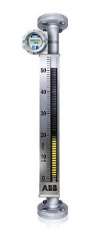
Magnetic Level Gauge Design and Operation

ABB / K-TEK Magnetic Level Gauge
Magnetic Level
Gauge (ABB / K-TEK)
Magnetic level gauges, also referred to as magnetic level indicators, are routinely used to provide a display of liquid level in tanks and other vessels. They are often employed in tandem with magnetostrictive, guided wave radar, or other measurement means to provide a reliable local display of liquid level, as well as an electrical signal that can be transmitted to recording instrumentation or controllers. The favorable attributes of magnetic level gauges include:
  • Continuous level measurement
  • Operable without electric power
  • Direct visual tank fluid level indication, regardless of tank shape or profile.
  • Wide range of operating temperature and pressure
  • Breakage resistant construction
  • Range of construction materials available to accommodate corrosive media
  • Measuring indicators, switches, and transmitters mounted externally, without contacting the medium being measured.
  • Low maintenance operation.
  • Readable level indication from greater distance than glass sight gauges.
  • Applicable to large fluid level ranges with a single instrument.
Magnetic level indicators have a strong position in the liquid level measurement field and should be considered as a candidate for fulfilling those applications where the magnetic level gauge features fulfill the project requirements. There are many options available to customize the level indicator for each specific application. Share your application challenges with a product specialist, combining your process knowledge with their product application expertise to develop an effective solution.

Take a Quick Tour of Swanson Flo

Take a minute (54 seconds actually) to acquaint yourself with Swanson Flo, one of the Midwest's most innovative process control companies. For more information, visit www.SwansonFlo.com.

Swanson Flo Minnesota Office Linecard

Swanson Flo's Minnesota Sales Office linecard.


Swanson Flo Wisconsin Sales Office Linecard

Here is the 2016 linecard from Swanson Flo's Wisconsin Sales Office:


Tech Sales & Marketing Linecard ( A Swanson Flo Company)

Tech Sales & Marketing, Inc., now a Swanson Flo company, is a manufacturers' representative and distributor serving the state of Indiana, Southwest Ohio and Kentucky for over 4 decades. Below id their current linecard: