Valve Actuation 101: The Three Basic Types of Pneumatic Valve Actuator

Pneumatic valve actuators come in three basic design varieties:
  1. Scotch-yoke
  2. Rack & pinion
  3. Rotary vane
All three types provide the same function - converting air pressure to rotational movement intended to open, close, or position a quarter-turn valve (ball valves, plug valves, butterfly valves, or other 90 degree rotational valves).

All three styles are available in either direct acting or spring return versions. Direct acting actuators use the air supply to move the actuator in both directions (open and close). Spring return actuators, as the name implies, uses springs to move the actuator back to its "resting" state. Converting from direct acting to spring return is done through simple modifications, typically just adding an external spring module, or removing the end caps from rack and pinion actuators and installing several coil springs.

Scotch yoke
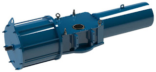
Scotch yoke (Limitorque)
Scotch-yoke actuators use a pneumatic piston mechanism to transfer movement to a linear push rod, that in turn engages a pivoting lever arm to provide rotation. They come in a wide variety of sizes, but are very often used on larger valves because they are capable of producing very high torque output. Spring return units have a large return spring module mounted on the opposite end of the piston mechanism working directly against the pressurized cylinder.

Rack and pinion
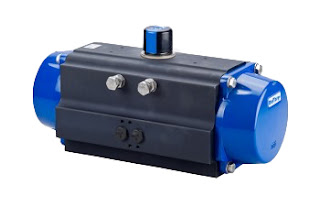
Rack and pinion (Delval)
A rack & pinion pneumatic actuator uses opposing pistons with integral gears to engage a pinion gear shaft to produce rotation. Rack & pinion actuators (sometimes referred to as a lunch box because of their shape) tend to be more compact than scotch yoke, have standardized mounting patterns, and produce output torques suitable for small to medium sized valves. They almost always include standard bolting and coupling patterns to directly attach a valve, solenoid, limit switch or positioner. Rack and pinion actuators use several smaller coil springs mounted internally and provide the torque to return the valve to its starting position.

Vane actuators generally provide the most space savings when comparing size-to-torque with rack and pinion and scotch yoke. They have a reputation for long life because then contain fewer moving parts than rack and pinion and scotch yoke actuators. Vane actuators use externally mounted, helically wound "clock springs" for their spring return mechanism.

The practical difference between these three types of pneumatic actuators comes down to size, power, torque curve and ease of adding peripherals. For the best selection of valve actuator for any quarter turn valve application, you should seek the advice of a qualified valve automation specialist. By doing so your valve actuation package will be optimized for safety, longevity, and performance.
Swanson Flo Markets - New Video

Here's a new short video highlighting the markets that Swanson Flo serves in the upper midwest United States.

Valve Automation Basics: Electric Actuators

Electric Actuator
Electric Actuator Assembly (Limitorque)
Electric actuators bring automation to industrial valve operation, allowing complex processes to be managed and controlled by remotely located control systems.

There are other motive forces used for valve actuators, including hydraulic and pneumatic, but electric actuators carry their own particular set of operating characteristics that make them an advantageous choice for many applications.

Valve actuators are available in uncountable variants to suit every application scenario. There are three basic valve actuation motions.

  • Multi-turn, with repeated rotations of the valve shaft needed to move the valve trim from fully open to fully closed. A gate valve is a multi-turn valve. These are also called linear, with respect to the motion of the closure element. The term "linear", in this case, refers only to the movement of the valve trim and not the flow characteristics of the valve.
  • Part Turn, where a 90 degree rotation of the valve shaft produces a change from opened to closed. Ball valves are in this category.
  • Lever, generally associated with damper control.

Electric Actuator
Completed Electrically Automated Valve
An electric actuator is a combination of motor and gearbox with sufficient torque to change valve trim position. A local self-contained control commands the motor and provides feedback to the process master controller regarding position, travel, torque, and diagnostics. Several interface options are available to facilitate communication between actuator and master controller.

There are numerous considerations to take into account when selecting an electric actuator.

  • Torque needed to effectively operate the subject valve.
  • Actuator enclosure type - wash down, hazardous area, dust, etc.
  • Service area for the assembly - corrosive environment, temperature extremes, and more
  • Valve movement - linear, multi-turn, part turn, lever
  • Operation mode - open and close only, positioning, modulating
  • Frequency or duty cycle - infrequent, frequent, or almost continuous positioning
  • Communication - How will the local controller communicate with the central control system?
  • Electrical - What electric power characteristics are available for operation?
  • Protections - Motor overload, torque limit, others
  • Process Safety - Among other things, what happens if power fails? 

There are certainly other elements to consider when applying an electric actuator for industrial use. Share your valve and actuator requirements and challenges with product specialists, combining your process knowledge with their product application expertise to forge the most effective solutions.

https://swansonflo.com
800-288-7926

Swanson Flo Performance - Full Capability Instrumentation and Valve Service & Repair

In-house repair as well as field service capabilities for process measurement and control.

Swanson Flo Performance supports every process control customer with region-based, full-capability service and repair. Both in-house and in-field. Built on more than 50 years of applications experience and technical knowledge.

  • From valves and instruments to actuation, fabrication and preventative maintenance. 
  • Our technicians are factory-certified. 
  • Shop is factory audited.
  • Total service for process measurement and control
  • Valve actuation facilities – the "Center of Excellence"
  • Instrument calibration, repair, and trouble-shooting services
Call 800-288-7926 or visit https://swansonflo.com


Limitorque MX Actuator Users Instructions, Maintenance, and Spare Parts Manual

Flowserve Limitorque MX
The Flowserve Limitorque MX actuator controls the opening and closing travel of valves and other actuated devices. OPEN and CLOSED limits are protected by an absolute encoder that provides optical sensing of valve position and measures valve position in both motor and handwheel operation.

No battery or backup power supply is required. Output torque is derived from motor speed, temperature, and voltage. If the preset torque is exceeded, the motor shuts off. As a result of this reliable and advanced protection technology, all valve and other actuated devices are protected from potential damage from overload, improper seating, and foreign obstructions.

A range of control and network options is available and can be easily added to the control capabilities already available on a standard actuator.

You can download the Limitorque MX Electronic Actuator User Instructions, Maintenance, and Spare Parts Manual in PDF version from the Swanson Flo site here (8.5MB), or read the embedded version below.

Turbine Flow Meters

Turbine flow meters
Turbine flow meters (Badger Meter / Blancett)
Turbine flow meters are process instruments used in a variety of industrial applications to measure the flow of a fluids. These types of flowmeters operate under the simple principle that the rotation of the turbine will be constant as the turbine is acted upon by a fluid passing through the flowmeter.

Turbine flow meters use the mechanical energy of the fluid to rotate a turbine blade in the flow stream and provide precise and accurate flow measurement. The flow impinging upon the turbine blades causes the rotor to spin. The angular velocity of a turbine flow meter is proportional to flow rate. The rotational velocity of the turbine is interpreted as an electrical frequency output through the use of magnetic pick-ups. As each turbine blade passes by the magnetic pick-up coil, a voltage pulse is generated which is a measure of the flow rate. The total number of pulses gives a measure of the total flow which can be totalized with a maximum error of a single pulse.

The relationship of the angle of the turbine meter blades to the flow stream governs the angular velocity and the output frequency of the meter. The sharper the angle of the turbine blade, the higher the frequency output.

Easy to maintain while also boasting reliability, turbine flow meters are known to be cost-effective solutions that make an ideal device for measuring flow rate. Aside from excellent rangeability, they also provide high response rate and high accuracy compared to other available types of flow meters. Turbine flow meters are sturdy, need very little maintenance, and seldom exhibit much deviation in performance.

Turbine flow meters
Turbine flow meters (Hoffer Flow Controls)
These meters are used in multiple industries to reliably measure the velocity of a variety of liquids, gases and vapors over a very broad range of flow rates, temperatures, and viscosities. Turbine flow meters are used to provide measurement information in cryogenic applications, crude oil production, chemical processing, blending systems, storage, off-loading, product loading, and many other applications across many industries.

Advantages:
  • Accuracy
  • Excellent repeatability and range
  • External power not required
  • Good fro cryogenic applications
  • Good for extreme pressures and temperatures
  • Easy to install
Disadvantages
  • Material availability
  • Not recommended for contaminated media or slurries
  • Error due to wear
For information on any flow control application, contact Swanson Flo by calling 800-288-7926 or visit https://swansonflo.com.

Disassembly, Repair, and Rebuild of the Jordan Mark 78 Control Valve

Jordan Mark 78 Control Valve
The Jordan Mark 78 pneumatic control valve is designed for accurate performance and simplified maintenance. This versatile product can be used on a variety of applications, including viscous/corrosive liquids, process gases or steam in process or utility service.
  • Shutoff: ANSI Class IV or VI
  • Sizes: 1/2" – 2" (DN15 – DN50)
  • End Connections: Threaded, Flanged, Socket Weld, Butt-Weld
  • Body Materials: Bronze, Carbon Steel, Stainless Steel
  • Cv (Kv): up to 50 (up to 43)
  • Trim Materials: Stainless Steel, Monel, Hastelloy C, Alloy 20
  • Seat: ANSI Class IV (Hard Seat); ANSI Class VI Teflon (Soft Seat)
  • Control Ranges: 3-15 psi, 6-30 psi or split ranges (0,2-1,0 bar, 0,4-2,1 bar)
The video below provides a detailed demonstration of how to disassemble, repair, and rebuild the Mark 78 control valve.

800-288-7926