Understanding Linear, Equal Percentage, and Quick Open Control Valve Flow Curves

Flowserve Valtek Control Valve
Flow characteristics, the relationship between flow coefficient and valve stroke, has been a subject of considerable debate. Many valve types, such as butterfly, eccentric disk and ball valves, have an inherent characteristic which cannot be changed (except with characterizable positioner cams). Flow characteristics of globe valves can be determined by the shape of the plug head.

The three most common types of flow characteristics are quick opening, equal percentage and linear. The figure below shows the ideal characteristic curve for each. These characteristics can be approximated by contouring the plug. However, inasmuch as there are body effects and other uncontrollable factors, plus the need for maximizing the flow capacity for a particular valve, the real curves often deviate considerably from these ideals. When a constant pressure drop is maintained across the valve, the characteristic of the valve alone controls the flow; this characteristic is referred to as the “inherent flow characteristic.” “Installed characteristics” include both the valve and pipeline effects. The difference can best be understood by examining an entire system.

Equal Percentage
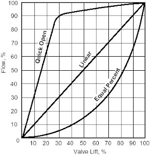
Control valve flow curves
Control valve flow curves.


Equal percentage is the characteristic most commonly used in process control. The change in flow per unit of valve stroke is directly proportional to the flow occurring just before the change is made. While the flow characteristic of the valve itself may be equal percentage, most control loops will produce an installed characteristic approaching linear when the overall system pressure drop is large relative to that across the valve.

Linear

An inherently linear characteristic produces equal changes in flow per unit of valve stroke regardless of plug position. Linear plugs are used on those systems where the valve pressure drop is a major portion of the total system pressure drop.

Quick Open

Quick open plugs are used for on-off applications designed to produce maximum flow quickly.

This information provided courtesy of Flowserve Valtek. Share your control valve requirements and challenges with a valve specialist, combining your own process knowledge and experience with their product application expertise to develop effective solutions.

Instruction Manual for Bronkhorst Mass Flow Pressure Meters and Controllers for Gases and Liquids

Bronkhorst MFC
Bronkhorst MFC
Bronkhorst offers the widest product range of thermal mass flow meters and controllers on the market. Numerous styles of both standard and specialized instruments can be offered for applications in laboratory, industrial and hazardous areas. Also, Bronkhorst specializes in (ultra) low flow Coriolis meters and controllers for liquids and gases.

For your convenience, below is the instruction manual for mass flow meters and controllers.


Contact Swanson Flo at 800-288-7926 or visit http://www.swansonflo.com for more information on Bronkhorst products.

Solenoid Valves - How They Work

Solenoid valve
Solenoid valve, 2-Way, Brass
(ASCO)
Solenoid valves are used throughout many commercial, municipal, industrial, and even residential settings to manage fluid flow. What we refer to as a solenoid valve is an integrated valve and actuator. The actuator, or solenoid, operates via electric current flowing through its helix shaped coil. Energizing the coil with a control signal produces a magnetic field, which then actuates the valve mechanism. Depending on the port configuration of the valve, solenoid valves can either function as two way flow controllers or as diverters in a process system, If the valve contains two ports, then the valve is an on/off valve. If the valve contains three or more ports, then the valve directs the flow of a fluid in the process system. Thanks to their flexibility, reliability, and need for only a small amount of control power, solenoid valves are a frequently used fluid process control device.

The solenoid used in a solenoid valve functions as a converter for electrical energy, using the supplied electrical energy to produce mechanical energy. Metal or elastomeric seals on solenoid valves can be coupled with electrical interfaces, allowing for relatively easy operation by the process controller. The valves typically use a metal plug to cover up a hole, and when pressure from the process fluid is applied to the valve, the pressure difference causes the solenoid valve to be in its normal position. Instead of referring to two directions of flow, the two-way solenoid valves are named two-way because these valves contain two valve ports which the fluid uses to travel.

Three way valves, similar to the name of the two-way valve, have three fluid ports. In an application example, these ports could correspond to pressure, exhaust, and cylinder. In a pneumatic system, these would be used for compressed air supply, vent, and the actuating mechanism. Regardless of the application, the valve function is the same, connecting the inlet port to one of two outlet ports. The selection array of solenoid valves for commercial and industrial use is vast, with variants suitable for a wide range of media, pressure, temperature, and operation sequence.

Pneumatic and hydraulic systems are typical applications for solenoid valves, as are processes such HVAC, where solenoid valves help control liquid refrigerant, as well as suction and hot gas lines. Solenoid valves are a popular fluid flow control options used in processing industries.

Share your fluid control requirements and challenges with application experts, combining your own process knowledge and experience with their product application expertise to develop effective solutions.

Watch the video below for more on how solenoid valves work.

Understanding the Relationship between Hydrostatic Pressure, Density and Level

Hydrostatic pressure
The pressure exerted by a fluid material in a vessel is directly proportional to its height multiplied by its density.

Hydrostatic pressure, or head pressure, is the force produced by a column of material. As the height of the material changes, there is proportional change in pressure. To calculate hydrostatic pressure, the density of the material is multiplied by the height of the column. The level of fluid in a column can be determined by dividing the pressure value by the density of the material.

To find pressure in a column of water, a gauge placed at the bottom of the vessel. With the water having a density of 0.0361 pounds per cubic inch, the level of the fluid is calculated by dividing the head pressure by the density of the fluid.

An example to determine the level measurement of a column of water that is 2 feet tall in diameter of 0.5 feet is solved by the following steps. The first step is measuring the weight of the vessel. Next measure the weight of the vessel with fluid. The weight of the fluid is determined by subtracting the weight of the vessel from the weight of the vessel with fluid. The volume of the fluid is then derived by dividing the fluid weight by the density of the fluid. The level of the fluid is finally calculated by dividing the volume of the fluid by the surface area.

Hydrostatic pressure can only be calculated from an open container. Within a closed vessel, or pressurized vessel, the vapor space above the column of material adds pressure, and results in inaccurate calculated values. The vessel pressure can be compensated for by using a differential pressure transmitter. This device has a high pressure side input and a low pressure side input. The high-pressure input is connected to the bottom of the tank to measure hydrostatic pressure. The low-pressure input of the differential pressure transducer is connected to the vapor space pressure. The transducer subtracts the vapor pressure from the high-pressure. Resulting is a value that represents the hydrostatic head proportional to the liquid level.

Electric Power Generation Using Coal

Electric Power Generation Using Coal
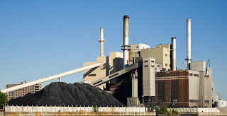
Coal Fired Power Plant
Electricity is generated at most electric power plants by using mechanical energy to rotate the shaft of electromechanical generators. The mechanical energy needed to rotate the generator shaft can be produced from the conversion of chemical energy by burning fuels or from nuclear fission; from the conversion of kinetic energy from flowing water, wind, or tides; or from the conversion of thermal energy from geothermal wells or concentrated solar energy. Electricity also can be produced directly from sunlight using photovoltaic cells or by using a fuel cell to electrochemically convert chemical energy into an electric current.

The combustion of a fossil fuel to generate electricity can be either: 1) in a steam generating unit (also referred to simply as a “boiler”) to feed a steam turbine that, in turn, spins an electric generator: or 2) in a combustion turbine or a reciprocating internal combustion engine that directly drives the generator. Some modern power plants use a “combined cycle” electric power generation process, in which a gaseous or liquid fuel is burned in a combustion turbine that both drives electrical generators and provides heat to produce steam in a heat recovery steam generator (HRSG). The steam produced by the HRSG is then fed to a steam turbine that drives a second electric generator. The combination of using the energy released by burning a fuel to drive both a combustion turbine generator set and a stream turbine generator significantly increases the overall efficiency of the electric power generation process.

Coal is the most abundant fossil fuel in the United States and is predominately used for electric power generation. Historically, electric utilities have burned solid coal in steam generating units. However, coal can also be first gasified and then burned as a gaseous fuel. The integration of coal gasification technologies with the combined cycle electric generation process is called an integrated gasification combined cycle (IGCC) system or a “coal gasification facility”. For the remainder of this document, the term “electric generating unit” or “EGU” is used to mean a solid fuel-fired steam generating unit that serves a generator that produces electricity for sale to the electric grid.

7 Important Considerations When Applying Inline, Spring-loaded Check Valves

Inline Spring-loaded Check Valve
(courtesy of CheckAll Valve)
1) Installation and Mounting
Inline, spring loaded check valves can be used in horizontal or vertical applications with proper spring selection. This is most evident in vertical flow down installations. The spring selected must be heavy enough to support the weight of the trim in addition to any column of liquid desired to be retained.

2) Elbow's, Tee's or other Flow Distorting Device's
Inline, spring loaded check valves are best suited for use with fully developed flow. Although there are many factors affecting the achievement of fully developed flow (such as media, pipe roughness, and velocity) usually 10 pipe diameters of straight pipe immediately upstream of the valve is sufficient. This is particularly important after flow distorting devices such as elbows, tees, centrifugal pumps, etc.

3) Valve Material Selection
There are many factors that influence the resistance of materials to corrosion, such as temperature, concentration, aeration, contaminants, and media interaction/reaction. Special attention must be paid to the process media and the atmosphere where inline check valves are applied. It is always recommended that an experienced application tech be consulted before installation.

4) Seat Material Selection

Several seat material options are available for inline, spring loaded check valves. An allowable leakage rate associated with the “metal-to-metal” as well as the PTFE o-ring seat, is 190 cc/min per inch of line size, when tested with air at 80 PSI. Resilient o-ring seats can provide a “bubble tight” shut-off (no visible leakage allowed at 80 PSI air).

5) Sizing and Spring Selection
It is very important to size check valves properly for optimum valve operation and service life. Sizing accuracy requires the valve be fully open, which occurs when the pressure drop across the valve reaches or exceeds three times the spring cracking pressure. Again, it is recommended that an experienced application tech be consulted for help with sizing.

6) Shock-Load Applications
Inline, spring loaded check valves are not designed for use in a shock-load environment, such as the discharge of a reciprocating air compressor. These types of applications produce excessive impact stresses which can adversely affect valve performance.

7) Fluid Quality
Inline, spring loaded check valves are best suited for clean liquids or gasses. Debris such as sand or fibers can prevent the valve from sealing properly or it can erode internal components or otherwise adversely affect valve travel. Any particles need to be filtered out before entering the valve.

8 Critical Control Valve Selection Criteria

Control Valve (Valtek)
Choosing an improperly applied sized or improperly sized control valve can have serious consequences on operation, productivity and most important, safety. Here is a quick checklist of basics that need to be considered:
  1. Control valves are not intended to be a an isolation valve and should not be used for isolating a process. 
  2. Always carefully select the correct materials of construction. Take into consideration the parts of the valve that comes in to contact with the process media such as the valve body, the seat and any other "wetted" parts. Consider the operating pressure and operating temperature the control valve will see. Finally, also consider the ambient atmosphere and any corrosives that can occur and effect the exterior of the valve. 
  3. Put your flow sensor upstream of the control valve. Locating the flow sensor downstream of the control valve exposes it to an unstable flow stream which is caused by turbulent flow in the valve cavity.
  4. Factor in the degree of control you need and make sure your valve is mechanically capable. Too much dead-band leads to hunting and poor control. Dead-band is roughly defined as the amount of control signal required to affect a change in valve position. It is caused by worn, or loosely fitted mechanical linkages, or as a function of the controller setting. It can also be effected by the tolerances from mechanical sensors, friction inherent in the the valve stems and seats, or from an undersized actuator. 
  5. Consider stiction. The tendency for valves that have had very limited travel, or that haven't moved at all, to "stick" is referred to as stiction. It typically is caused by the valves packing glands, seats or the pressure exerted against the disk. To overcome stiction, additional force needs to be applied by the actuator, which can lead to overshoot and poor control.
  6. Tune your loop controller properly. A poorly tuned controller causes overshoot, undershoot and hunting. Make sure your proportional, integral, and derivative values are set). This is quite easy today using controllers with advanced, precise auto-tuning features that replaced the old fashioned trial and error loop tuning method.
  7. Don't over-size your control valve. Control valves are frequently sized larger than needed for
    Control Valve Specialized Kammer
    Control Valve
    Specialized for Food/Bev
    Pharmaceutical (Kammer)
    the flow loop they control. If the control valve is too large, only a small percentage of travel is used (because a small change in valve position has a large effect on flow), which in turn makes the valve hunt. This causes excessive wear. Try to always size a control valve at about 70%-90% of travel.
  8. Think about the type of control valve you are using and its inherent flow characteristic. Different types of valve, and their disks, have very different flow characteristics (or profiles). The flow characteristic can be generally thought of as the change in rate of flow in relationship to a change in valve position. Globe control valves have linear characteristics which are preferred, while butterfly and gate valves have very non-linear flow characteristics, which can cause control problems. In order to create a linear flow characteristic through a non-linear control valve, manufacturers add specially designed disks or flow orifices which create a desired flow profile.
These are just a few of the more significant criteria to consider when electing a control valve. You should always discuss your application with an experienced application expert before making your final selection.