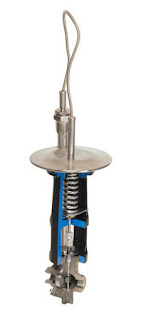
A Proven Actuator Ideal for Valves Requiring Rotary or Linear Movement

Limitorque L120 electric actuator
Limitorque L120 electric actuator.
Whether used with gate valves, globe valves, penstocks or sluice gates, versatile Limitorque L120 Series actuators operate without modification in any rising or non-rising stem application for linear-action valves.

When combined with a Limitorque WG or HBC series quarter-turn gear operator, L120 actuators can also be used to control butterfly, ball and plug valves, as well as damper drives, flop gates or any other device which requires rotary movement.

L120 actuators are specified for use in petrochemical, power generation, and water and waste treatment applications where failure of a single actuator can be extremely costly … even catastrophic.

For more information on Limitorque actuators, visit Swanson Flo's website or call 800-288-7926.

For your convenience, below you will find the Limitorque L120-85 installation and operation manual.


What are purged impulse lines and why are they needed?

Purged impulse lines
Diagram of a purged impulse line implementation.
(image courtesy of Lessons in Industrial Instrumentation
by Tony R. Kuphaldt
)
Purged impulse lines, or sensing lines, allow process transmitters and gauges to maintain operation under potentially adverse process conditions that may impact the operation or accuracy of the instrument. The purging of an impulse line is of particular use when sensing lines may have a high susceptibility to plugging by the process fluid. The line is purged with clean fluid at a constant rate, meaning new fluid is always being introduced into the impulse line. When the purge is properly set, a critical element of successful implementation, the pressure instrument is still able to correctly measure system pressure.

Purging a sensing line will require additional valves and devices to properly control the purge fluid flow and provide for effective maintenance or repair. Because of the increased relative complexity, a purging setup will likely be employed only in cases where other methods of maintaining clear sensor lines and proper instrument operation have been considered and rejected. The impulse line will stay free of sedimentation thanks to the purge fluid, and process fluid contamination of the sensing line is avoided.

One of the most important parts of the purged impulse line system is a restriction, implemented to prevent the pressure instrumentation from sensing the elevated pressure of the purge fluid supply instead of measuring the original process fluid. The purge valve, through which the purge fluid flows, is left partially open instead of fully open. If the restriction does not mitigate the introduction of the purge fluid on the process line, then the flow rate of the purge fluid can adversely impact the process measurement. It is essential that purge flow be regulated in a manner that does not adversely impact the measurement of actual process conditions.

A basic requirement of sensing line purge systems is that the supply of purge fluid needs to be flowing at all times. Additionally, the purge fluid supply pressure must be maintained at a level greater than the process pressure because if the pressure of the purge fluid supply drops below the process pressure, the process fluid will flow into the impulse line. The purge fluid must also not react negatively with or contaminate the process and will be continuously consumed. Generally, purge rates are kept as low as possible, mitigating purge fluid impact on the process measurement and keeping the cost low. A rotameter, which indicates visual flow of the purge fluid, is an item typically paired with purge impulse line systems, and there are many options available for use as purge fluids.

Common gases for purged impulse lines include air, nitrogen, and carbon dioxide. A purge system can be applied to both gas and liquid process systems. Share your process measurement challenges with instrumentation specialists. Combine your own process knowledge and experience with their product application expertise to develop effective solutions.

Fundamentals of Thermal Mass Flow Measurement

Sage Prime Thermal Mass Flow Meter
Thermal Mass Flow Meter
Courtesy of Sage Metering
“Why do we need to measure in mass flow? What is the difference between ACFM and SCFM? Why are pressure and temperature correction not required when measuring with a thermal mass flow meter? What is the thermal mass flow measurement theory? What are common applications to use thermal mass flow meters?” The white paper below attempts to explain these questions and more. 

The original Sage Metering Document titled "Fundamentals of Thermal Mass Flow Measurement" can be downloaded here.

Swanson Flo Performance

Specialists in valves, automation and instrumentation, Swanson Flo Performance sets the standard for process control optimization and training that maximizes plant uptime, safety and operating efficiency.
  • Valve automation center 
  • Experienced staff of factory-certified technicians 
  • Responsive on-call repair and service 
  • Extensive OEM parts inventory 
  • Third party audited standards 
  • The region’s widest range of industry application experience 
  • Comprehensive multi-brand process equipment knowledge
Please take a minute to watch the video below for more information.

Self-Operating Temperature Regulators

Jordan Mark 80
Jordan Mark 80
In process control applications, exceedingly close control with PID loops is not always necessary. There can also be instances where location or operational circumstance calls for temperature control, but not necessarily under the control of a centralized system. Self operated mechanical temperature regulators, with their reliable and simple operating scheme, can be well suited for these applications.

Self operated temperature regulators are basically valves with self contained actuation controlled by a filled system, or bulb. The valve portion of the assembly controls the flow of a fluid which impacts the process temperature. The process temperature is measured by a fluid filled bulb, connected via a capillary to a chamber containing a diaphragm. As the temperature of the process changes, the fluid in the bulb expands or contracts, changing the fluid pressure on the diaphragm. Pressure on the diaphragm causes movement, which is linked to the sliding gate trim of the valve, thus adjusting fluid flow. A spring provides a counteractive force on the diaphragm and allows for setpoint adjustment.

The self contained assembly requires no external power source to operate and requires little maintenance. Proper selection of line size, capillary length, bulb type, and temperature range are key elements in getting the right valve for the job. Application temperature ranges from -20 to +450 degrees Fahrenheit.

The Mark 80 Series Temperature Regulator features the advanced sliding gate seat technology pioneered by Jordan Valve. Using the Jordan Valve sliding gate seat technology, the Mark 80 temperature regulators have the signature straight-through flow, short-stroke that is 1/3 of a globe-style valve, quiet operation and tight shutoff. The Jordan Valve Mark 80 has high rangeability and extremely accurate regulation. The proprietary Jorcote seat material is extremely hard (@RC85) with a low coefficient of friction that delivers outstanding performance and long service life.
Share your temperature control and fluid flow challenges with product application specialists, combining you own process expertise with their product application know-how to develop the most effective solutions.

You can see all the details in the datasheet included below. For more information contact Swanson Flo by calling 800-288-7926 or visit http://www.swansonflo.com.

Choosing Temperature Sensors for Industrial HVAC and Chiller Equipment

Minnesota, Iowa, Wisconsin, Nebraska, Illinois, Indiana, North Dakota, South Dakota, Montana, Wyoming, Michigan,
Sensors used in HVAC
Reprinted with permission from Gems Sensors & Controls white paper.

Efficient operation of industrial HVAC and chiller equipment depends upon optimum temperatures of refrigerant and lubricating oil at various phases of the refrigeration cycle. The most common sensors for this purpose utilize negative temperature coefficient (NTC) thermistors of various resistance values. NTC sensor devices exhibit lower electrical resistance when exposed to higher temperatures.

RTD for HVAC
RTD
Either thermistor or RTD-type sensors may be used for this purpose, however thermistors are preferred for most applications due to cost and media exposure attributes. RTDs are more expensive, and the fragility of the sensing element require it to be separated from the sensed media within an enclosure. Thermistors are more durable, and may be immersed directly in any non-conductive fluid media being sensed, for quicker response to temperature changes. There is an inherent non- linearity in thermistor output that requires temperature and resistance correction for the output. Manufacturers of thermistors, and sensors made from them, can provide Resistance-to-Temperature curves for this purpose.

Assuming equivalent thermistor quality and resistance values, combining the thermistor within a housing that can be installed into HVAC or chiller equipment is what differentiates one sensor assembly from another. These fall into two basic types: exposed or enclosed thermistor housings.
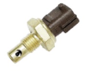
Open thermistor probe
Open sensor thermistor probe.
Exposed thermistors directly contact the fluid being sensed; in this application, those are refrigerant, oil, and oil/refrigerant emulsion, although they may be used in any non-conductive fluid. Direct contact with fluids provides faster and more accurate thermistor response. The downside to exposed thermistor sensors is leakage through the housing where the thermistor leads pass through sensor housings, especially in pressured installations. Leakage results in maintenance downtime for the operator and warranty issues for the equipment manufacturer.

Enclosed thermistors encase the thermistor inside a probe that is an integral part of the housing. These eliminate the leakage issue, but because the thermistor is actually in an air pocket surrounded by the metal or plastic housing, temperature compensation and sensor responsiveness issues are introduced.


A Recent Third Option

Gems Sensors & Controls has produced a third type of housing that combines the performance of an exposed thermistor design, while providing the hermetic sealing of an enclosed sensor housing. Known as the TM-950 Series, these thermistor-based temperature sensors were designed specifically to solve long-term reliability issues in HVAC and Chiller applications.

TM-950 Series temperature sensor incorporates a unique fused-glass technique to produce a hermetically sealed the housing. Molten glass is placed inside the heated housing. As the assembly cools the metal housing shrinks, compressing the glass. In addition, the boundary surface of heated metal and glass bond at a molecular level. Two nickel-plated steel tubes are positioned pre-positioned before the glass fusing process to provide a pass through for the thermistor leads. Any of a variety of thermistors may be utilized based on the temperature sensing profile required. Once leads are passed through the steel tubes and glass, induction soldering fills the tubes completely, providing a leak-proof seal to 450 psig. The result is a sensor with the benefits of direct fluid contact incorporating the leak-proof attributes of an enclosed sensor.

For more information on selecting sensors for industrial HVAC applications and chillers visit Swansonflo.com or call 800-288-7926

Happy Fourth of July from Swanson Flo

"We hold these truths to be self-evident, that all men are created equal, that they are endowed by their Creator with certain unalienable Rights, that among these are Life, Liberty and the pursuit of Happiness. — That to secure these rights, Governments are instituted among Men, deriving their just powers from the consent of the governed, — That whenever any Form of Government becomes destructive of these ends, it is the Right of the People to alter or to abolish it, and to institute new Government, laying its foundation on such principles and organizing its powers in such form, as to them shall seem most likely to effect their Safety and Happiness."

THOMAS JEFFERSON, Declaration of Independence